Filter

A filter and filtrate technology, applied in filtration and separation, fixed filter element filters, chemical instruments and methods, etc., can solve the problems of reducing the amount of catalyst, decreasing production capacity, accumulating filters, etc., to maintain stable production, Avoid fluctuations and maintain a stable effect

Inactive Publication Date: 2014-10-08
NANJING COLLEGE OF CHEM TECH
View PDF4 Cites 3 Cited by
  • Summary
  • Abstract
  • Description
  • Claims
  • Application Information

AI Technical Summary

Problems solved by technology

With the prolongation of time, in the area far from the inlet and outlet of the circulating liquid of the filter, the catalyst concentration in the reaction circulating mixed liquid will gradually increase, causing the catalyst to accumulate in the filter, and the amount of catalyst that the reaction system participates in the reaction decrease in production capacity
[0009] (3) When the catalyst accumulates in the filter, the general production load will drop by more than 10%, and the load will drop by 25%-35% in severe cases. The filter has to be shut down, which affects the production capacity and stable operation of the device.
[0010] Currently, there is a lack of a filter that prevents catalyst build-up

Method used


Image

  • Filter
  • Filter

Examples


Embodiment 1

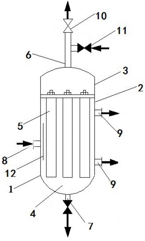
[0034] Such as figure 1 As shown, a filter 1 of the present invention, the filter 1 includes a cylinder body 2, an upper head 3 and a lower head 4; the cylinder body 2 is provided with a filter element 5, and the outer wall of the cylinder body 2 There is a circular tube;

[0035] The upper part of the cylinder body 2 is provided with an upper head 3, and the top of the upper head 3 is provided with a filtrate discharge / recoil liquid inlet 6; the filtrate discharge / recoil liquid inlet 6 is the same port ;

[0036] The bottom of the cylinder body 2 is provided with a lower head 4, and the lower head 4 is provided with a discharge port 7;

[0037] The side wall of the cylinder 2 is provided with a reaction circulation liquid inlet 8 and a reaction circulation liquid outlet 9;

[0038] The filtrate discharge / backflush inlet 6 is connected to the regulating valve 10 and the backflush valve 11 respectively;

[0039] The reaction circulation liquid outlet 9 is one or more; the a...

Embodiment 2

[0056] The difference between embodiment 2 and embodiment 1 is that there are three reaction circulation liquid outlets 9 , and the reaction circulation liquid outlet 9 and the reaction circulation liquid inlet 8 are evenly distributed on the same circumference of the cylinder 2 . The circumferential position is half the length of the cylinder body 2 .

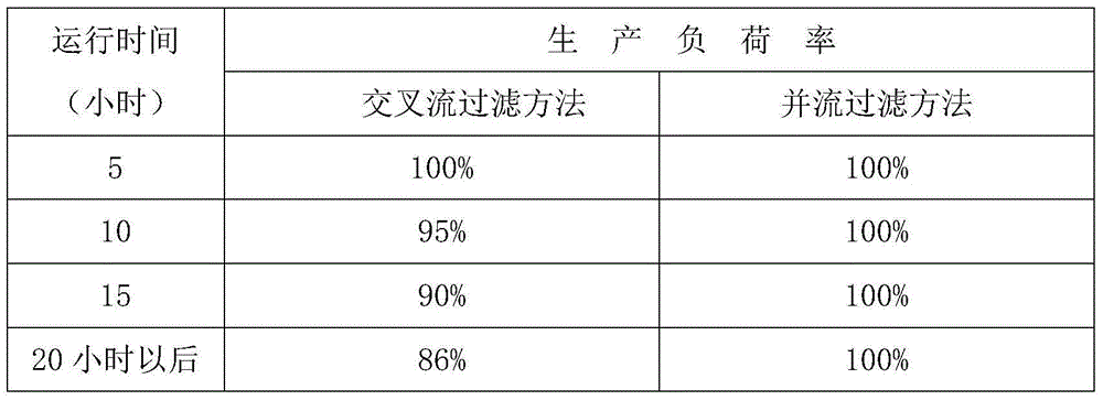
[0057] Table 1 shows the change of the production load rate of the cross-flow filtration method and the co-flow filtration method under the same conditions as the operating time of the device increases. It is not difficult to see the accumulation of the catalyst in the filter 1. Under the same reaction conditions, the accumulation of the catalyst in the filter 1 can be known from the reduction of the production load rate.

[0058] Table 1

[0059]

[0060] From the comparative comparison in Table 1, it can be seen that the co-current filtration method can effectively prevent the accumulation of catalyst in the filter 1, so...


PUM

PropertyMeasurementUnit
angleaaaaaaaaaa

Abstract

The invention discloses a filter which comprises an internally hollow cylinder, an upper head and a lower head, wherein the cylinder is internally provided with a filter element; a circular ring pipe is arranged on the outer wall of the cylinder; the upper head is arranged at the upper part of the cylinder; a filter fluid discharging hole / back flushing fluid inlet is arranged at the top of the upper head; the lower head is arranged at the bottom of the cylinder; a discharging hole is formed in the lower head; a reaction circulating fluid inlet and one or more reaction circulating fluid outlets are formed in the side wall of the cylinder; the filter fluid discharging hole / back flushing fluid inlet is respectively connected with an adjusting valve and a back flushing valve; the included angle alpha between the reaction circulating fluid outlet and the reaction circulating fluid inlet is greater than 0 degree and less than 360 degrees; the reaction circulating fluid outlet is connected with the circular ring pipe; a main outlet is formed in the circular ring pipe. According to the filter, a concurrent flow filter method is used, so that catalyst particles are prevented from accumulating in the filter and then a reaction system keeps high-load stable continuous running.

Description

technical field [0001] The invention relates to the field of chemical equipment, in particular to a filter. Background technique [0002] At present, filters composed of filter elements of various materials are being used more and more widely in the fields of chemical industry, medicine, water treatment and environmental protection, and the wide application of turbidity tube filter element filter is one of them. [0003] The existing technology generally adopts a cross-flow filtration scheme. For example, in the production process of hydroxylamine phosphate salt solution, the reaction circulating liquid flowing from the head tank to the filter, its feed port is on the side wall of the filter, and the circulating discharge port is on the filter side wall. Below the device, this filtering method leaves a dead angle when the reaction circulating liquid flows. Especially when the filter diameter is large, in the area away from the inlet and outlet of the circulating fluid, the ...

Claims


Application Information

Patent Timeline
Patent Type & Authority Applications(China)
IPC IPC(8): B01D29/52B01D29/66
Inventor 汤立新丁志平季锦林
Owner NANJING COLLEGE OF CHEM TECH
Why Eureka
Try Eureka