Hydraulic device for miniature numerical control machine tool

A technology for CNC machine tools and hydraulic devices, applied in the field of hydraulic devices, can solve the problems of easy locking of cylinders, easy corrosion of machine tools and water generation, etc., and achieves the effect of simple structure and improved work stability.

Inactive Publication Date: 2014-10-08
JIANGSU AIBO MACHINERY MFG
View PDF0 Cites 0 Cited by
  • Summary
  • Abstract
  • Description
  • Claims
  • Application Information

AI Technical Summary

Problems solved by technology

[0002] In the known small CNC machine tools, air cylinders are usually used to control the quick clamping of the rotary cylinder, but in actual operation, it is found that this structure has the following disadvantages: 1. The air pump connected to the cylinder will generate water during work, which is easy to corrode the machine tool equipment; 2. When the machine tool is running at high speed, the cylinder is easy to lock, which makes the clamping work impossible

Method used


Image

  • Hydraulic device for miniature numerical control machine tool

Examples


Embodiment Construction

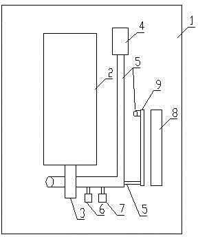
[0011] Depend on figure 1 A hydraulic device for a small numerically controlled machine tool is composed of an oil tank 1, an oil supply device and an oil circuit cooling device; the oil supply device and the oil circuit cooling device are arranged in the middle and right parts of the oil tank 1; The oil supply device includes a drive motor 2, an oil pump 3, a single-head solenoid valve 4, an oil pipe 5, a pressure regulating valve 6 and a pressure gauge 7; the oil circuit cooling device includes an oil pipe 5, a cooling fan 8 and a heat sink 9 .

[0012] When working, the drive motor 2 drives the oil pump 3 to extract the hydraulic oil from the oil tank 1 and divide it into two paths, one path passes through the oil pipe 5 and delivers it to the single-head solenoid valve 4 through the pressure regulating valve 6 and pressure gauge 7 in turn. 7 to adjust the pressure regulating valve 6 to control the oil pressure in the oil pipe 5 within the working requirements. The single-...


PUM


Abstract

The invention relates to a hydraulic device for a miniature numerical control machine tool, which consists of an oil tank (1), an oil supply device and an oil way cooling device, wherein the oil supply device comprises a drive motor (2), an oil pump (3), a single-head solenoid valve (4), an oil pipe (5), a pressure regulating valve (6) and a pressure gauge (7); the oil way cooling device comprises the oil pipe (5), a cooling fan (8) and a heat-radiating plate (9). The hydraulic device is characterized in that the oil supply device is arranged at the middle part of the oil tank (1), and the oil way cooling device is arranged on the right of the oil tank (1). The hydraulic device has the benefits that the locking problem of a rotary oil cylinder is solved through replacing an original air pressure way with oil pressure; moreover, the hydraulic device has a simple and light structure, and the working stability of the numerical control machine tool is also effectively improved.

Description

technical field [0001] The invention relates to a hydraulic device, especially a hydraulic device for a small numerically controlled machine tool. Background technique [0002] In the known small CNC machine tools, air cylinders are usually used to control the quick clamping of the rotary cylinder, but in actual operation, it is found that this structure has the following disadvantages: 1. The air pump connected to the cylinder will generate water during work, which is easy to corrode the machine tool equipment; 2. When the machine tool is running at high speed, the cylinder is easy to lock, which makes the clamping work impossible. Contents of the invention [0003] In view of the above deficiencies, the object of the present invention is to provide a hydraulic device for a small CNC machine tool, which can ensure the normal operation of the quick clamping of the rotary cylinder. [0004] The technical solution of the present invention is achieved in the following manner...

Claims


Application Information

Patent Timeline
Patent Type & Authority Applications(China)
IPC IPC(8): B23Q3/00F15B11/08
CPCB23Q3/082
Inventor 汪海潮
Owner JIANGSU AIBO MACHINERY MFG
Why Eureka
Try Eureka