Pneumatic sliding plate type vehicle blocking device

A pneumatic skateboard and car-stopping technology, which is applied in the directions of transportation and packaging, railway car body parts, and forced railway car stoppers, etc., can solve the problems of heavy installation workload, high labor intensity of staff, and failure of car stoppers to raise the foundation, etc. Achieve the effect of improving the deformation resistance strength and impact strength and reducing labor intensity

Active Publication Date: 2014-10-08
TIANCHEN COAL MINE OF ZAOZHUANG MINING GRP
View PDF8 Cites 3 Cited by
  • Summary
  • Abstract
  • Description
  • Claims
  • Application Information

AI Technical Summary

Problems solved by technology

[0003] 1. The workload of installing the foundation is heavy. Since the foundation of φ108 pipe body and steel plate processing is more than 500mm in length, it is necessary to excavate more than 500mm to install the foundation during installation.
[0004] 2. The labor intensity of the staff is high during use. Since the φ89 steel pipe is equipped with a handle to block the vehicle, the length of the stick is 1200mm, and it is installed in the foundation. When using it, the workers must overcome the self-weight of the stick and its length of 500mm to lift the stick The body proposes the foundation to release the minecart
[0005] 3. During the use of the φ89 steel pipe block body, when blocking the mine car, the joint between the stick body and the foundation bears shear force, which is easy to deform and cannot play a good role in blocking the mine car
[0006] 4. In the case of the arrival of the mine car, at present, this kind of car stick can not be put forward. To release the mine car, the underground dispatching winch must be used to pull in the opposite direction before the car stop stick can be raised to release the mine car.

Method used


Image

  • Pneumatic sliding plate type vehicle blocking device
  • Pneumatic sliding plate type vehicle blocking device
  • Pneumatic sliding plate type vehicle blocking device

Examples


Embodiment Construction

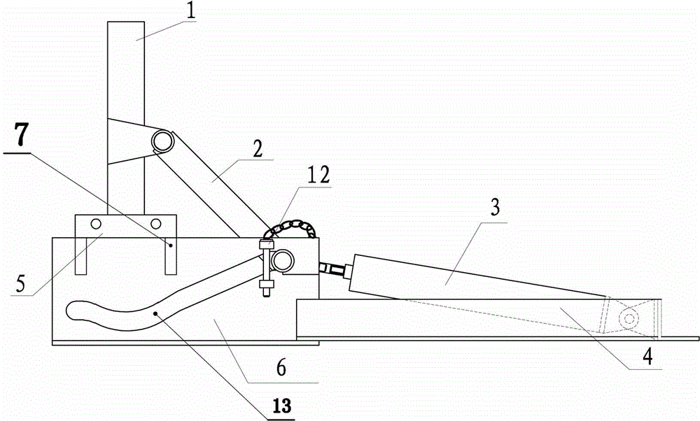
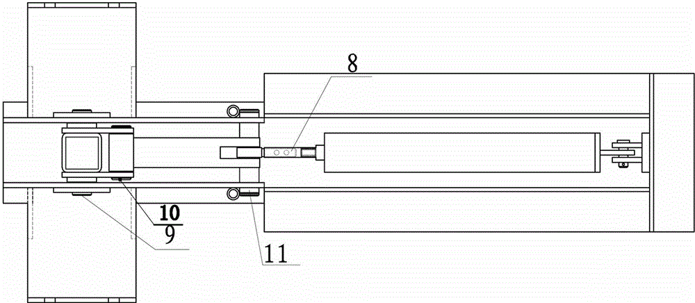
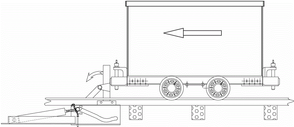
[0022] The present invention comprises cylinder 3, support bar 2, stop bar 1 and frame, and frame is made up of two parts of chute plate 6 and frame 4, and chute plate 6 is connected with frame 4 together, and frame 4 rear end side plate Cylinder 3 is hinged on the cylinder block, and cylinder 3 is contained in frame 4 inside, and two side plates of chute plate 6 are connected with stop bar 1 by car stop rotating shaft 9, and the supporting rotating shaft 10 on the car stop bar 1 is also hinged with Support rod 2, the other end of support rod 2 is also connected with sliding shaft 11, and sliding shaft 11 is contained in the inside of the chute 13 of two side plates of chute plate 6, and the head end of cylinder 3 piston rod is hinged on the slide through connecting rod 8. on axis 11. The chute 13 is a hollow groove with a circular arc transition milled out on the side plate, and the width of the chute 13 is greater than or equal to the outer diameter of the sliding shaft 11 ....


PUM


Abstract

A pneumatic sliding plate type vehicle blocking device can improve strength and the effect of blocking a mine car. The technical scheme is that the pneumatic sliding plate type vehicle blocking device comprises a cylinder, a supporting rod, a vehicle blocking rod and a machine frame. The machine frame is composed of a sliding groove plate and a frame. The sliding groove plate is connected with the frame, the cylinder is hinged to a cylinder seat on a side plate at the tail of the frame and installed in the frame, two side plates of the sliding groove plate are connected with the vehicle blocking rod through a vehicle blocking rotating shaft, a supporting rod is further hinged to a supporting rotating shaft on the vehicle blocking rod, the other end of the supporting rod is further connected with a sliding shaft, the sliding shaft is installed in sliding grooves of the two side plates of the sliding groove plate, and the head end of a cylinder piston rod is hinged to the sliding shaft through a connecting rod. The pneumatic sliding plate type vehicle blocking device can remarkably alleviate labor intensity of workers, and deformation resistance strength and impact bearing strength of the whole vehicle blocking device are improved.

Description

technical field [0001] The invention relates to a protective facility for electromechanical transportation in coal mines, in particular to a special pneumatic slide plate type vehicle blocking device for coal mines. Background technique [0002] Coal mine underground inclined roadway transportation is generally equipped with three protective facilities, which are arranged in turn in the three protective facilities of the parking lot, respectively. Car barrier. The car blocking rods used in coal mines are all simple. They are made of φ89 steel pipes equipped with handles as the body of the car blocking rods, and the basis is processed by φ108 pipe body and steel plate. The two are used together. There are the following problems in this present car stop stick: [0003] 1. The workload of installing the foundation is heavy. Since the foundation of φ108 pipe body and steel plate processing is more than 500mm in length, it is necessary to excavate more than 500mm during instal...

Claims


Application Information

Patent Timeline
Patent Type & Authority Applications(China)
IPC IPC(8): B61K7/16
Inventor 魏振全周忠鹏李勇白景峰于绍波姜楠章征峰韩兆清魏继杰张红伟杜善营
Owner TIANCHEN COAL MINE OF ZAOZHUANG MINING GRP
Why Eureka
Try Eureka