Magnetic rotation type spindle yarn feeding mechanism

A magnetic spinning, spindle technology, applied in the direction of conveying filamentous materials, thin material processing, transportation and packaging, etc., can solve problems such as yarn breakage, and achieve the effect of preventing tearing and running evenly and smoothly up and down.

Active Publication Date: 2014-10-08
南通通州江华纺织有限公司
View PDF3 Cites 3 Cited by
  • Summary
  • Abstract
  • Description
  • Claims
  • Application Information

AI Technical Summary

Problems solved by technology

However, when the yarn is wound on the spindle, the traditional feeding mechanism mostly uses a four-bar or cam mechanism, but the four-bar and cam mechanism are constantly moving during work. the yarn will break
Moreover, once the design and assembly of the four-bar mechanism or the cam mechanism is completed, the height of its up and down movement has been determined, so that the traditional spindle feeding mechanism can only be applied to a spindle of one height.

Method used


Image

  • Magnetic rotation type spindle yarn feeding mechanism
  • Magnetic rotation type spindle yarn feeding mechanism

Examples


Embodiment Construction

[0010] Below in conjunction with embodiment the present invention is further described:

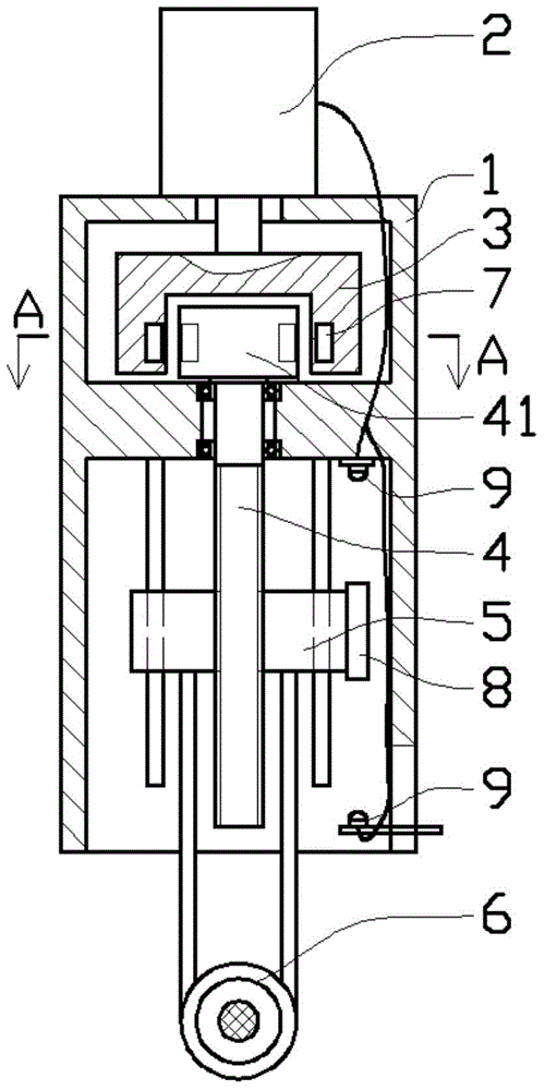
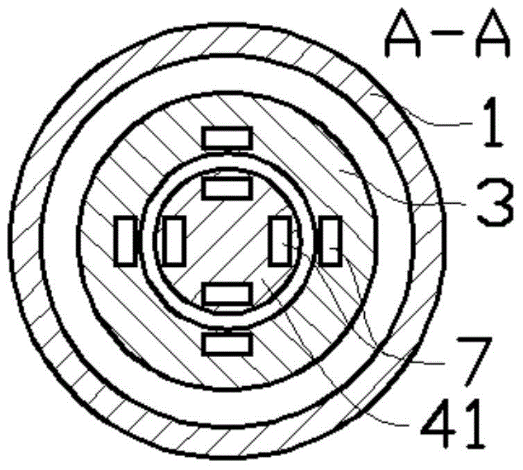
[0011] Such as figure 1 with figure 2 As shown in the embodiment, the magnetic rotary spindle thread feeding mechanism includes a housing 1, a micro motor 2, a transmission block 3, an adjustment screw 4, a sliding block 5, and a yarn guide ring 6; the housing 1 is cylindrical, The micro motor 2 is assembled on the upper part of the housing 1, the output shaft of the micro motor 2 is coaxial with the housing 1, the output shaft goes deep into the housing 1 and is connected with the transmission block 3, and the adjusting screw rod 4 The upper part of the rotating block 41 is fixed, and the lower part of the adjusting screw 4 is designed with a screw thread structure, and the adjusting screw 4 is coaxially assembled with the housing 1 . The rotating block 41 and the transmission block 3 are driven by the small magnetic block 7 corresponding to the position, and the sliding block 5 is as...


PUM


Abstract

The invention provides a magnetic rotation type spindle yarn feeding mechanism. The magnetic rotation type spindle yarn feeding mechanism comprises a shell, a micro motor, a transmission block, an adjusting lead screw, a sliding block and a yarn guiding ring. The micro motor is assembled on the upper portion of the shell, an output shaft of the micro motor is coaxial with the shell and stretches deeply into the shell to be connected with the transmission block, a rotating block is fixed to the upper portion of the adjusting lead screw, transmission between the rotating block and the transmission block is achieved through small magnetic blocks which correspond in position, the sliding block is assembled on the lower portion of the adjusting lead screw through a lead screw structure capable of sliding up and down, the yarn guiding ring extending out of the lower portion of the shell is assembled on the lower portion of the sliding block through a connecting rod, and the micro motor is a motor rotating forward and reversely. According to the magnetic rotation type spindle yarn feeding mechanism, the transmission block is driven by the micro motor to rotate, the adjusting lead screw is driven to rotate by using magnetic force through the transmission block, and therefore transmission control over the sliding block is achieved.

Description

technical field [0001] The invention relates to the technical field of textile machinery, in particular to a magnetic rotary spindle thread feeding mechanism. Background technique [0002] Spindle, that is, the drum on the spinning machine. According to the needs of spinning, it can be equipped with different roving or spun yarns. The more yarns on the machine, the higher the spinning efficiency. In the current factories, the spinning process is usually completed by the spinning machine, but the spun yarn is collected by rotating the spindle. In order to ensure that the spindle is in a regular cylindrical or conical barrel shape when receiving the yarn, usually A yarn feeding mechanism is installed in front of the spindle, so that the yarn moves up and down periodically in the tangential direction of the spindle. This allows the yarn to be evenly wound on the spindle. However, when the yarn is wound on the spindle, the traditional feeding mechanism mostly uses a four-bar ...

Claims


Application Information

Patent Timeline
Patent Type & Authority Applications(China)
IPC IPC(8): B65H54/30B65H59/38B65H63/02
Inventor 杨伯娟钱末丫戴晨
Owner 南通通州江华纺织有限公司
Why Eureka
Try Eureka