
Bridge pier protecting device

A technology of protective devices and bridge piers, applied in shipping equipment, climate change adaptation, etc., can solve problems such as large damage to bridges, affecting waterways, and ship crashes, improving versatility and applicability, and good impact energy consumption. , Improve the effect of corrosion resistance

Inactive Publication Date: 2014-10-08
方义飞
View PDF5 Cites 4 Cited by
  • Summary
  • Abstract
  • Description
  • Claims
  • Application Information

AI Technical Summary

Problems solved by technology

[0002] With the development of economy and transportation, large-scale cross-sea and cross-river bridges are constantly being built. The rivers and seas where these bridges are located are busy waterways, and the conditions of wind, waves, and water flow are very complicated. The risk of ship collision; as the tonnage of the ship increases, at a certain speed, once it collides with the pier, not only the ship will be destroyed, but the strong impact force will cause deformation, twisting and even damage to the pier , the bridge is very likely to collapse, resulting in very serious consequences
[0003] At present, the commonly used pile group method, thin-shell sand cofferdam method, and artificial island method are generally suitable for occasions with shallow water and good geological conditions. give up without
In addition, such as a bridge protective device disclosed in the invention patent with the publication number CN 103696401 A, although it is relatively convenient to maintain and can float up and down on its own with the rise and fall of the water level, the anti-collision ring will still be directly damaged after being hit by a ship, etc. When it hits the bridge pier, the local damage effect on the bridge is greater

Method used


Image

  • Bridge pier protecting device
  • Bridge pier protecting device
  • Bridge pier protecting device

Examples


Embodiment Construction

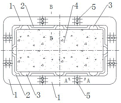
[0041]The purpose of the present invention is to provide a bridge pier protective device, which has a simple structure, is easy to maintain, can float up and down by itself with the rise and fall of the water level, and will not be directly damaged when it is hit by a ship or the like. Bridge piers, and also have the characteristics of high reliability and high efficiency.

[0042] In order to enable those skilled in the art to better understand the technical solutions of the present invention, the present invention will be further described in detail below in conjunction with the accompanying drawings and specific embodiments. It should be noted that, in the case of no conflict, the embodiments in the present application and the features in the embodiments can be combined with each other.

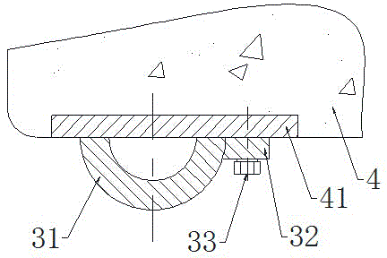
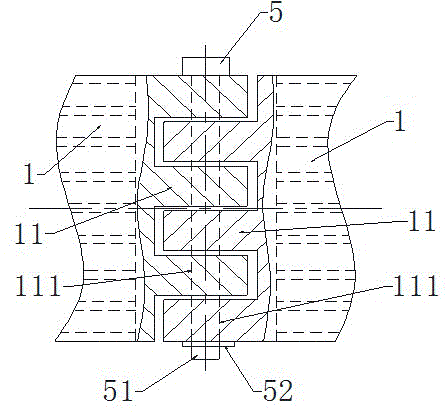
[0043] Such as figure 1 and figure 2 as shown, figure 1 It is a schematic diagram of the assembly structure of the bridge pier protection device provided by a specific embodiment of th...


PUM


Abstract

The invention discloses a bridge pier protecting device, and belongs to the field of construction safety. The bridge pier protecting device is mainly used for safety protection of a pier of a bridge and comprises a ridge track group arranged on the periphery of the pier, a striking energy consumption pillar group consisting of a plurality of striking energy consumption pillars as well as a plurality of connecting components connected among the striking energy consumption pillars, wherein the striking energy consumption pillar group formed by connecting the plurality of striking energy consumption pillars through the plurality of connecting components surrounds the pier, and the striking energy consumption pillar group can slide up and down along the ridge track group. The bridge pier protecting device has the characteristics that the structure is simple, the maintenance is convenient, the device can automatically float up and down with rising and falling of the water level and cannot directly damage the pier when struck by a ship and the like, the reliability and the efficiency are high and the like.

Description

technical field [0001] The invention relates to the field of building safety such as bridges, in particular to a bridge pier protection device. The invention is mainly developed for the protection of bridge piers, and is generally used for the protection of bridge piers of bridges crossing seas and rivers. It is therefore convenient to describe the invention in relation to this use, but it should be understood that the invention may be used for alternative beam or column protection. Background technique [0002] With the development of economy and transportation, large-scale cross-sea and cross-river bridges are constantly being built. The rivers and seas where these bridges are located are busy waterways, and the conditions of wind, waves, and water flow are very complicated. The risk of ship collision; as the tonnage of the ship increases, at a certain speed, once it collides with the pier, not only the ship will be destroyed, but the strong impact force will cause deform...

Claims


Application Information

Patent Timeline
Patent Type & Authority Applications(China)
IPC IPC(8): E02B3/26
CPCY02A30/30
Inventor 方义飞
Owner 方义飞
Learn More