A photovoltaic hydraulic control device for a valve

A control device and hydraulic technology, applied in valve device, valve operation/release device, fluid pressure actuating device, etc., can solve the problem of unable to meet the needs of valve operation in water transfer projects, and unable to realize automatic pipeline adjustment, opening and closing. Close by manual control and other problems, to achieve the effect of high energy utilization efficiency, compact shape and elimination of water hammer

Active Publication Date: 2016-08-24
WUHAN DAYU VALVE
View PDF5 Cites 0 Cited by
  • Summary
  • Abstract
  • Description
  • Claims
  • Application Information

AI Technical Summary

Problems solved by technology

[0002] In long-distance water diversion projects (such as the South-to-North Water Diversion Project), due to geographical constraints or wiring cost constraints, a rather long part of the pipeline is not covered by the grid, and the opening and closing of the valves in this part of the pipeline are manually controlled. Automated line adjustments are therefore not possible
At the same time, due to the water hammer effect, the valve operation control on the long-distance water pipeline has strict requirements, including the switching mode and speed (for example, the valve is required to be closed in stages, and the speed of each stage can be adjusted in a wide range), the existing manual control will open When the valve is closed suddenly, the water flow will generate a certain pressure on the valve, which will cause the valve to be damaged
In addition, conventional photovoltaic systems only use photovoltaic power control in areas covered by power grids. When the power is insufficient, it cannot meet the needs of valve operation in water transfer projects.

Method used


Image

  • A photovoltaic hydraulic control device for a valve
  • A photovoltaic hydraulic control device for a valve
  • A photovoltaic hydraulic control device for a valve

Examples


Embodiment Construction

[0020] The present invention will be further described below in conjunction with accompanying drawing.

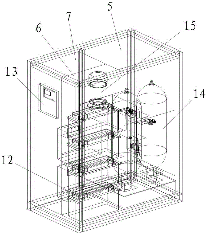
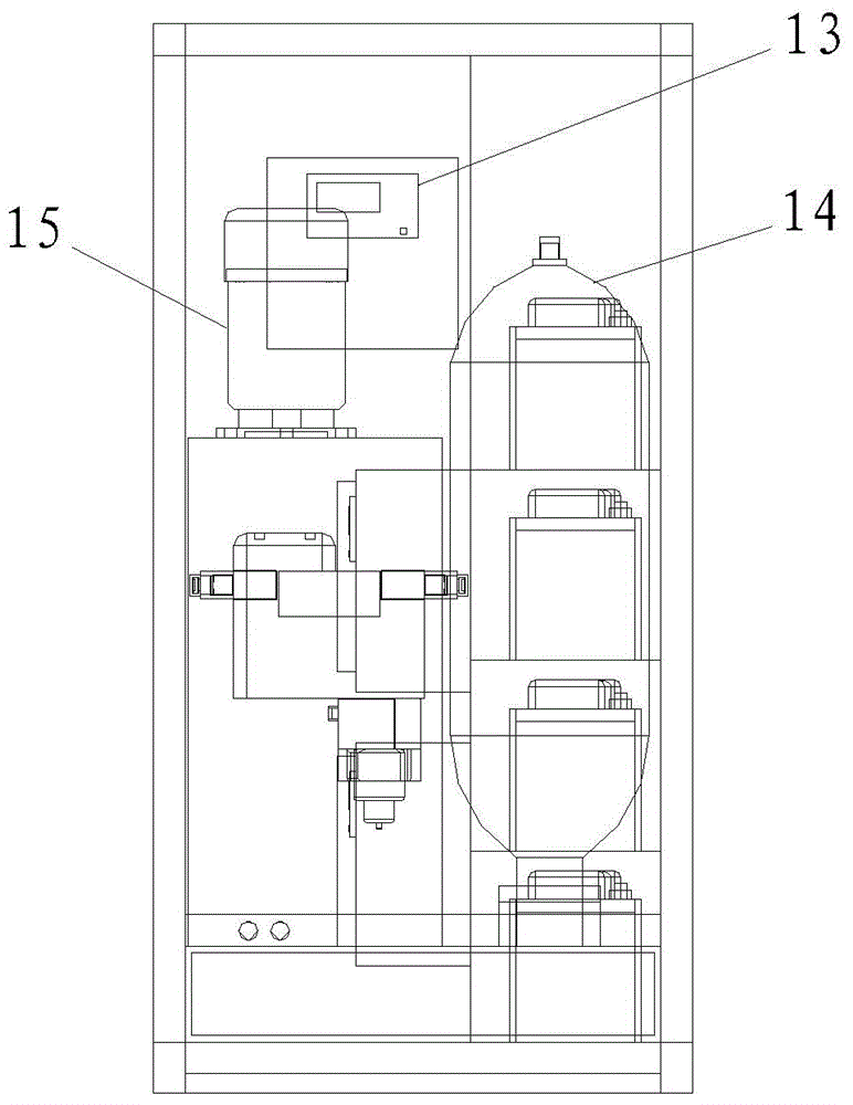
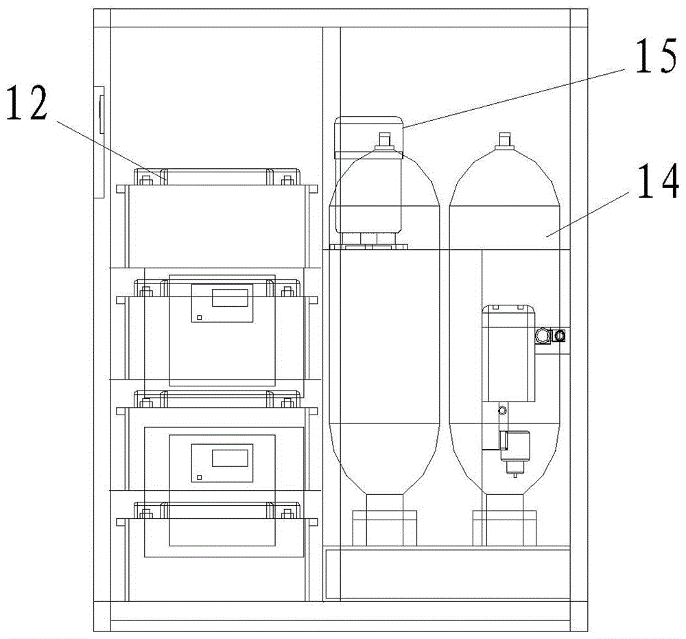
[0021] Such as Figure 1-4 As shown, the interior of the photovoltaic hydraulic drive box 2 is divided into three partitions adjacent to each other along the longitudinal direction, that is, the first partition 5, the second partition 6 and the third partition 7, wherein the first partition 5 is provided with A hydraulic system 11 , a photovoltaic battery 12 is provided in the second compartment 6 , and a charge controller 8 , an inverter 9 , a frequency converter 10 and a control system 13 are provided in the third compartment 7 . The charging controller 8, the inverter 9, the frequency converter 10 and the hydraulic system 11 are electrically connected in sequence, the photovoltaic battery 12 is connected to the charging controller 8, and the control system 13 is connected to the charging controller 8 and the inverter 9 respectively. , the frequency converter 10 is elect...


PUM


Abstract

The invention belongs to the technical field of valve control, and particularly relates to a photovoltaic hydraulic control device of a valve. The photovoltaic hydraulic control device of the valve comprises a photovoltaic hydraulic drive box, wherein the interior of the photovoltaic hydraulic drive box is longitudinally divided into three adjacent compartments; a hydraulic system is arranged inside the first compartment; a photovoltaic storage battery is arranged inside the second compartment; a charge controller, an inverter, a frequency converter and a control system are arranged inside the third compartment; the hydraulic system comprises a hydraulic accumulator, a hydraulic control circuit, an oil tank and a motor oil pump. The photovoltaic hydraulic control device of the valve can achieve remote monitoring, and can regulate and control flow or pressure of a pipeline in the absence of a power grid in a flexible control mode; with photovoltaic energy as primary energy and hydraulic oil as secondary energy storage, the photovoltaic hydraulic control device of the valve can work both in the presence of electricity and in the absence of electricity, with high energy utilization efficiency.

Description

technical field [0001] The invention belongs to the technical field of valve control, and in particular relates to a photovoltaic hydraulic control device for a valve. Background technique [0002] In long-distance water diversion projects (such as the South-to-North Water Diversion Project), due to geographical constraints or wiring cost constraints, a rather long part of the pipeline is not covered by the grid, and the opening and closing of the valves in this part of the pipeline are manually controlled. Automated line adjustments are therefore not possible. At the same time, due to the water hammer effect, the valve operation control on the long-distance water pipeline has strict requirements, including the switching mode and speed (for example, the valve is required to be closed in stages, and the speed of each stage can be adjusted in a wide range), the existing manual control will open When the valve is closed suddenly, the water flow will generate a certain pressure...

Claims


Application Information

Patent Timeline
Patent Type & Authority Patents(China)
IPC IPC(8): F16K31/02F16K31/12F15B1/02F15B11/08F15B13/04F15B21/04
CPCF15B1/02F15B13/04F15B20/00F15B21/08F16K31/12
Inventor 李习洪孙高峰
Owner WUHAN DAYU VALVE
Why Eureka
Try Eureka