
Intelligent leakage current monitoring sensing device and leakage current monitoring system

A leakage current and sensing device technology, which is applied in measuring devices, measuring current/voltage, measuring electrical variables, etc., can solve problems such as potential safety hazards, on-site operation existence, strong electromagnetic interference of sampling signals, etc.

Inactive Publication Date: 2014-10-08
保定市瑞高电气有限公司
View PDF9 Cites 3 Cited by
  • Summary
  • Abstract
  • Description
  • Claims
  • Application Information

AI Technical Summary

Problems solved by technology

[0004] 1. The electromagnetic discharge counter is mainly used to record the number of discharge actions of the overvoltage protector or arrester, and cannot monitor the leakage current value during normal operation. The electromagnetic discharge counter is not intelligent and cannot upload the data to the background
[0005] 2. The sensor of the overvoltage online monitor is installed on the base of the overvoltage protector, and the sensor and the host are connected with a cable. The problem with this implementation method is that the sampling signal is susceptible to strong electromagnetic interference in the cabinet when it is transmitted through the cable; The secondary equipment cannot be reliably isolated, and there are potential safety hazards in on-site operation
[0006] At the same time, the overvoltage online monitor is an independent device. Although it has a communication interface, its operating data cannot be uploaded because the box transformer is far away from the monitoring master station.

Method used


Image

  • Intelligent leakage current monitoring sensing device and leakage current monitoring system

Examples


Embodiment Construction

[0018] The principles and features of the present invention are described below in conjunction with the accompanying drawings, and the examples given are only used to explain the present invention, and are not intended to limit the scope of the present invention.

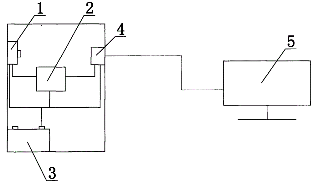
[0019] Please refer to figure 1 , figure 1 It is a structural schematic diagram of a leakage current monitoring system in an embodiment of the present invention.

[0020] The present invention provides an intelligent leakage current monitoring and sensing device, comprising: a leakage current acquisition component 1 for detecting leakage current, a CPU processor 2 with a logic operation function, and a self-powered power supply 3 for supplying power to electrical components and a wireless communication component 4 for wireless communication; the wireless communication component 4 of the leakage current collection component 1 and wireless communication is connected with the CPU processor 2; the self-powered power su...


PUM


Abstract

The invention discloses an intelligent leakage current monitoring sensing device and a leakage current monitoring system. The intelligent leakage current monitoring sensing device comprises a leakage current collecting assembly, a CPU processor, a self power supply and a wireless communication assembly. The leakage current collecting assembly and the wireless communication assembly used for wireless communication are in signal connection with the CPU processor, the self power supply is electrically connected with the leakage current collecting assembly, and the CPU processor is electrically connected with the wireless communication assembly. By means of the intelligent leakage current monitoring sensing device, collected data can be sent to a box change monitoring assembly in a wireless mode to be used for on-line monitoring of an overvoltage protector or a lightning arrester. The leakage current monitoring system comprises a host and the intelligent leakage current monitoring sensing device. The intelligent leakage current monitoring sensing device comprises the CPU processor and the wireless communication assembly which is in signal connection with the CPU processor. The wireless communication assembly is in wireless connection with the host. The intelligent leakage current monitoring sensing device and the box change monitoring assembly are in wireless communication, so that physical separation between primary equipment and secondary equipment is achieved, and thus system operation security is improved.

Description

technical field [0001] The present invention relates to the technical field of electric power monitoring equipment, and more specifically relates to an intelligent leakage current monitoring sensor device and a leakage current monitoring system. Background technique [0002] The overvoltage protector or arrester installed in the box-type transformer of the power system is mainly to unload the energy generated by the system due to lightning strikes and operating overvoltage, and to avoid damage to primary equipment. By monitoring the change of continuous leakage current and the number of operations, it is possible to effectively detect abnormalities such as internal aging and moisture, and avoid running with faults. [0003] At present, the methods for real-time monitoring of overvoltage protectors on the market include: [0004] 1. The electromagnetic discharge counter is mainly used to record the number of discharge actions of the overvoltage protector or arrester, and can...

Claims


Application Information

Patent Timeline
IPC IPC(8): G01R19/00
Inventor 韦青松李俊海
Owner 保定市瑞高电气有限公司
Learn More