Optimized and optimally-cutting reactive compensation method and reactive compensation device

A compensation method and compensation controller technology are applied in the directions of reactive power compensation, reactive power adjustment/elimination/compensation, etc., to achieve the effect of saving operating costs, facilitating production, and facilitating selection and implementation of applications.

Inactive Publication Date: 2014-10-08
AEROSPACE SCI & IND SHENZHEN GROUP
View PDF4 Cites 19 Cited by
  • Summary
  • Abstract
  • Description
  • Claims
  • Application Information

AI Technical Summary

Problems solved by technology

[0008] The technical problem to be solved by the present invention is to avoid the deficiencies of the prior art and to propose a reactive power compensation method based on a reactive power compensation controller and a reactive power compensation device. Optimizing the switching capacitor method, and judging the control strategy through the composite physical quantity of three-phase voltage, three-phase reactive power and power factor, thus effectively overcoming the limitation of sequential switching and cyclic switching that need to be equipped with equal-capacity capacitors, It improves the control precision, overcomes the limitation of the capacitive capacity by code switching, effectively prevents the switching oscillation at light load and insufficient compensation at heavy load, and achieves the effect of universal application, convenience and flexibility, fast and accurate switching

Method used


Image

  • Optimized and optimally-cutting reactive compensation method and reactive compensation device
  • Optimized and optimally-cutting reactive compensation method and reactive compensation device
  • Optimized and optimally-cutting reactive compensation method and reactive compensation device

Examples


Embodiment Construction

[0062] Further details will be given below in conjunction with the embodiments shown in the accompanying drawings.

[0063] The present invention proposes an optimal reactive power compensation method based on a reactive power compensation controller, such as Figure 1 to Figure 5 As shown, including the following steps A to F:

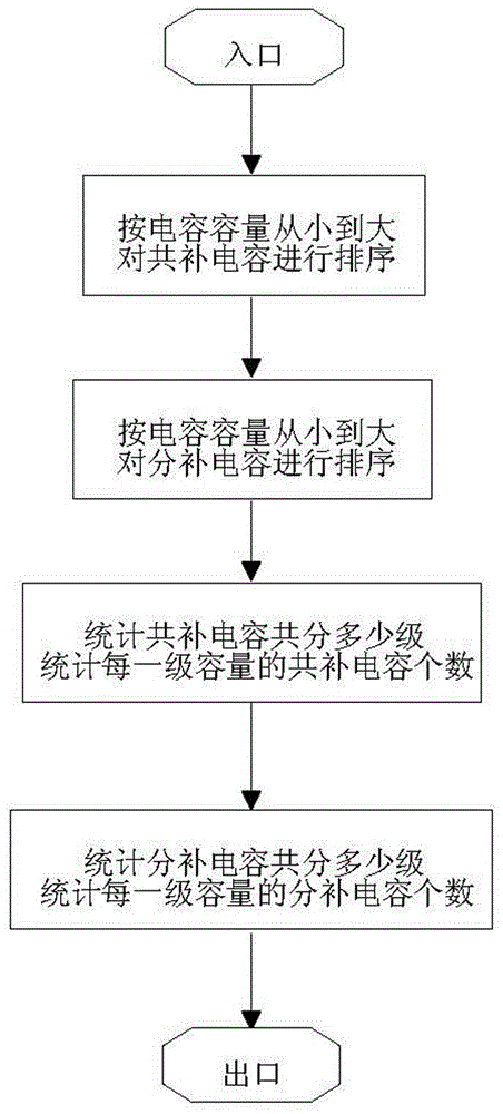
[0064] A. Determine the capacity level of the common compensation capacitor according to the parameters set by the reactive power compensation controller, the number of capacitors in each capacity level of the common compensation capacitor, the capacity level of the sub-compensation capacitor, and the number of capacitors in each capacity level of the sub-compensation capacitor .

[0065] Preferred embodiments of the present invention, such as figure 1 As shown, step A specifically includes the following sub-steps,

[0066] A1. According to the parameters set by the reactive power compensation controller, determine the capacity of the common compen...


PUM


Abstract

The invention provides an optimized and optimally-cutting reactive compensation method and reactive compensation device. The method can judge a control strategy through composite physical quantity of three-phase voltage, three-phase reactive power and power factors to form a capacitor switching strategy of cutting off a capacitor and optimizing and optimally cutting a switching capacitor step by step, and accordingly reactive compensation can be accurately finished. The capacitor switching strategy uses a switching capacitor optimizing and optimally cutting method to optimize the core portion of the reactive compensation method based on work timing of an input capacitor. The optimized and optimal-cutting capacitor switching strategy is simple, practical and easy to achieve, can carry out intelligent control switch to a common compensation capacitor and a divided compensation capacitor, can meet the application requirements and accuracy requirements of reactive compensation of most low-voltage distributing networks and brings convenience to design, debugging, operation and using of a reactive compensation controller.

Description

technical field [0001] The invention relates to a control method and a control device for electric power supply and distribution, in particular to a reactive power compensation method and a reactive power compensation device for a distribution network. Background technique [0002] The reactive power compensation controller is the core component of the reactive power compensation device, and the reactive power compensation control method is one of the key technologies in the reactive power compensation controller. The compensation control method mainly includes two parts: switching judgment strategy and switching capacitor selection strategy. [0003] The switching judging strategies in the prior art are divided into power factor control mode, voltage control mode, reactive current control mode, reactive power control mode and compound control mode according to the control physical quantity. The composite control method further includes a composite control method of voltage...

Claims


Application Information

Patent Timeline
Patent Type & Authority Applications(China)
IPC IPC(8): H02J3/18
CPCY02E40/30
Inventor 徐飞赖晓明
Owner AEROSPACE SCI & IND SHENZHEN GROUP
Why Eureka
Try Eureka