
System for reducing the wiping gas consumption in an air knife

A technology of pressurized gas and air flow, which is applied in the direction of drying gas arrangement, device for coating liquid on the surface, rearrangement of coated substances, etc., and can solve problems such as thermal expansion and deformation of nozzles

Active Publication Date: 2014-10-08
COCKERILL MAINTENANCE & INGIE
View PDF6 Cites 1 Cited by
  • Summary
  • Abstract
  • Description
  • Claims
  • Application Information

AI Technical Summary

Problems solved by technology

Due to temperature differences, this causes thermal expansion and deformation of the opening along the entire nozzle

Method used


Image

  • System for reducing the wiping gas consumption in an air knife
  • System for reducing the wiping gas consumption in an air knife
  • System for reducing the wiping gas consumption in an air knife

Examples


example

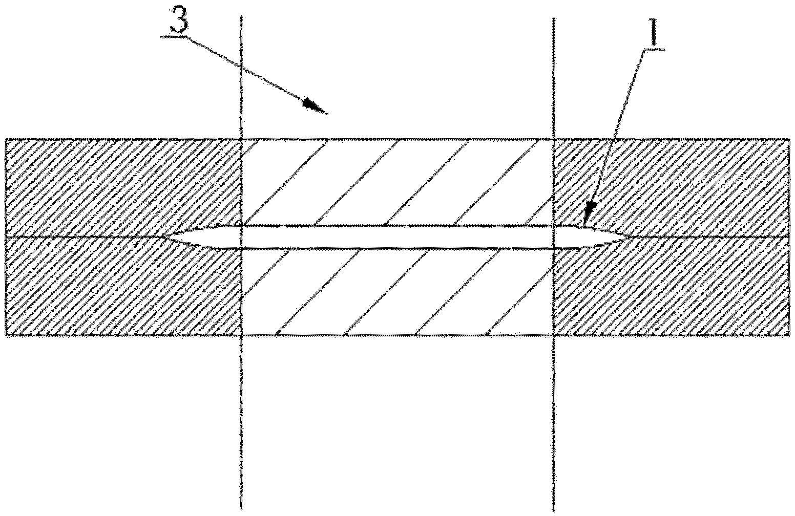
[0049] When putting this reduction into practice, an embodiment of the device according to the invention is first installed on a gas wiping nozzle (not shown).

[0050] In this example, the nozzle 1 is about 2.3 m long; the opening 4 of this nozzle may be between 1 mm and 2 mm.

[0051] The cable 9 has a diameter of 5 mm and is applied or withdrawn by means of a carriage with two sheaves 6, 7, of which there is one carriage 10 on each side of the nozzle. The carriage is moved by a motor powered screw. The internal movement of the carriage 10 is limited by carriage stoppers 12 .

[0052] Tested using an internal pressure of 220mb in the chamber and a very small Pitot tube (Pitot tube) at the outlet ( Figure 8 ) to measure dynamic pressure. On the right side of the figure it can be observed that the dynamic stress can be significantly reduced where the cable is applied. A detailed analysis of the results showed that the residual flow at the applied cable was approximately 1...


PUM

PropertyMeasurementUnit
diameteraaaaaaaaaa
diameteraaaaaaaaaa

Abstract

The present invention relates to a device for controlling the thickness of a coating made of a liquid film on a moving strip (3), characterised in that said automated means for reducing the gas flow at each of said nozzle sides comprise a moving carriage (10) guiding a retractable cable (9) able to be applied respectively onto and out of the gas discharge opening (4), inside the nozzle chamber (5) and in that, at each transversal side of the nozzle (1), a transition, between an external nozzle section where the gas flow is reduced and an internal nozzle section where the gas flow is not reduced, is assured by means of two together-moving grooved wheels or pulleys (6, 7) connected to the moving carriage (10), located side by side and having their axis perpendicular to the nozzle, so that the cable (9) is successively located against the opening (4); on an external side of the first pulley (6), between the two pulleys (6, 7) and distant from the opening (4) on an internal side of the second pulley (7).

Description

technical field [0001] The invention relates to a gas wiping device for controlling the thickness of a liquid film deposited on a running strip. Typical examples are devices intended for gas wiping of liquid metals, such as those obtained by hot dip coating, on wide coated steel sheets. Background technique [0002] The "air knife" method is a well known process for wiping off excess liquid entrained by the running strip from the bath. Typical air knives use chamber pressures of up to 700mbar, which result in exit airflow velocities close to sound levels. The gas discharge opening is typically in the range of 0.5mm to 2mm. [0003] The gas wiping process creates some waves in the coating due to the high turbulence that occurs when the gas jet enters the atmosphere. High turbulence cannot be reduced due to high levels of shear. However, the amplitude of these waves tends to decrease with time due to the leveling process that occurs in the liquid state driven by the surfac...

Claims


Application Information

Patent Timeline
Patent Type & Authority Applications(China)
IPC IPC(8): B05C11/06B05B1/00B05B1/30C23C2/20F26B21/00B21B45/02
CPCD21H25/16F26B13/28D21H19/00C23C2/003B05B1/005B05B1/3033B05C11/06F26B21/004C23C2/20B05B11/06C23C2/14
Inventor 米歇尔·杜波依斯布赖斯·范豪特
Owner COCKERILL MAINTENANCE & INGIE
Learn More