Liquid iron slag filter

A filter and iron slag technology, applied in the direction of fixed filter element filter, filtration separation, solid separation, etc., can solve the problems of shortened filter element service life, filter element damage, equipment blockage, etc., to strengthen adsorption capacity and improve filtration capacity. , to avoid the effect of direct impact

Inactive Publication Date: 2014-10-15
SICHUAN KAIMING INVESTMENT
View PDF0 Cites 1 Cited by
  • Summary
  • Abstract
  • Description
  • Claims
  • Application Information

AI Technical Summary

Problems solved by technology

[0003]The purpose of the present invention is to overcome the problem that the liquid that needs to be filtered directly hits the filter element at high speed, which is very easy to cause damage to the filter element, and the existence of iron slag is easy to cause damage to the filter element The service life is greatly shortened, and the defects that cause blockage to the equipment provide a liquid iron slag filter

Method used


Image

  • Liquid iron slag filter

Examples


Embodiment

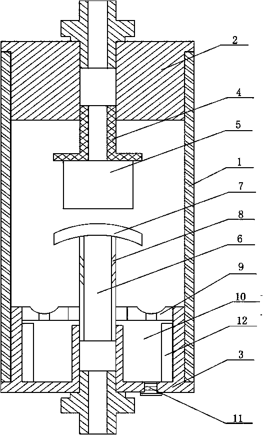
[0018] Such as figure 1 As shown, the liquid iron slag filter of the present invention includes a housing 1. On both ends of the housing 1, an upper head 2 and a lower head 3 are respectively installed, and the upper head 2 and the lower head 3 are both provided with communication A filter joint 4 is installed on the communicating hole of the upper head 2, a filter element 5 is installed on the filter joint 4, a spray tube 6 is installed on the communicating hole of the lower head 3, and the end of the spray tube 6 is installed The baffle 7 is provided with a plurality of spray holes 8 on the side wall of the spray pipe 6, and a filter plate 9 is sleeved on the spray pipe 6. The filter plate 9, the lower head 3, and the side wall of the housing 1 are enclosed to form a settlement In the chamber 10, an adsorption magnet 12 is installed in the settling chamber 10, and a discharge hole and a matching seal 11 are provided on the lower head 3, and the seal 11 can be disassembled to...


PUM


Abstract

The invention discloses a liquid iron slag filter. The liquid iron slag filter comprises a shell, two ends of the shell are provided with an upper end closure and a lower end closure respectively, the upper enclosure and the lower end closure are respectively provided with a communicating pore, the communicating pore of the upper end closure is provided with a filtering joint, the filtering joint is provided with a filter core, the communicating pore of the lower end closure is provided with a jet tube, the tail end on the jet tube is provided with a baffle plate, the sidewall of the jet tube is provided with a plurality of jet holes, a filtering plate is sleeved to the jet tube, a settling chamber is formed between a filter plate and the lower end closure, and an adsorption magnet is arranged in the settling chamber. The adsorption magnet arranged in the settling chamber can adsorb iron slag in a liquid to make the iron slag settled in the settling chamber as possible, so the settling efficiency and the iron slag adsorption efficiency are improved.

Description

technical field [0001] The invention relates to a filter, in particular to a liquid iron slag filter. Background technique [0002] Liquid filter is an indispensable device on the conveying medium pipeline. It is usually installed at the inlet end of pressure reducing valve, pressure relief valve, fixed water level valve or other equipment to eliminate impurities in the medium and protect the valve and equipment. Normal use. When the fluid enters the filter cartridge with a filter screen of a certain specification, its impurities are blocked, and the clean filtrate is discharged from the filter outlet. When cleaning is required, just take out the detachable filter cartridge and reinstall it after treatment. Yes, therefore, it is extremely convenient to use and maintain. At present, in equipment using liquid as a working medium, the liquid is usually pumped into the control device through a pump, and the control device then guides the liquid into the working device. Due to...

Claims


Application Information

Patent Timeline
IPC IPC(8): B01D29/90B03C1/30
Inventor 曾维亮
Owner SICHUAN KAIMING INVESTMENT
Why Eureka
Try Eureka