

Cast-in-place externally prestressed concrete-filled steel pipe pile and construction method thereof and support pile wall
A technology of steel pipe concrete piles and external prestressing, which is applied in the direction of sheet pile walls, foundation structure engineering, construction, etc., and can solve the problem of large amount of steel bars and concrete in cast-in-situ piles, high transportation and leasing costs of section steel, and increased use costs of section steel, etc. problems, achieve good economic benefits, avoid removal loss, and reduce transportation costs
- Summary
- Abstract
- Description
- Claims
- Application Information
AI Technical Summary
Problems solved by technology
Method used
Image

Examples
Embodiment 1
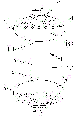
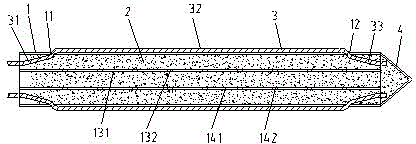
[0041] refer to figure 1 , figure 2 with Figure 5 , a cast-in-place external prestressed steel pipe concrete pile, comprising: a steel pipe 1, a concrete layer 2 cast in-situ inside the steel pipe 1 and a plurality of prestressed tendons 3 arranged on the steel pipe 1, the The prestressed tendons are arranged along the axial direction of the steel pipe 1, including a top section 31, a middle section 32 and a bottom section 33. The middle section 32 is located outside the steel pipe 1, and the top section 31 and bottom section 33 penetrate the steel pipe wall and enter the inside of the steel pipe. , the bottom section 33 extends into the concrete layer 2 and is closely combined with the concrete layer 2. The top section 31 is partly combined with the concrete layer 2, and part of the concrete layer 2 is exposed. The exposed part is used for piles After the body reaches the design strength, external prestressing is carried out to the prestressed tendons. The present inventi...
Embodiment 2
[0053] The second embodiment of the present invention is basically the same as the first embodiment, the main difference is that: the middle section of the prestressed tendon is wrapped with a sheath tube, and the two ends of the sheath tube are connected with the upper through hole and the lower through hole respectively. The holes are matched with each other and sealed with a sealing ring. In this embodiment, a sheath tube is added outside the middle section. The sheath tube can be a plastic tube, which can protect the prestressed tendons from the erosion of external water, and fully guarantees the prestressed reinforcement. High strength and performance of stress tendons.
[0054] In addition, there are the following differences. In this embodiment, the distance between the upper through holes and the upper end surface of the steel pipe is 2m, and the structural design is reasonable, which ensures the smooth application of external prestressing. The plurality of upper throu...
Embodiment 3
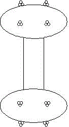
[0056] refer to image 3 with Image 6 , the third embodiment of the present invention is basically the same as the first embodiment, the main difference is: the prestressed tendons have 2~6 ( image 3 The one shown in is 6), which are divided into two groups, and the two groups of prestressed tendons are symmetrically arranged, and each group of 1~3 prestressed tendons is close together to form a whole, with a simple structure and a reasonable design.
[0057] In addition, there are the following differences. In this embodiment, the distance between the upper through holes and the upper end surface of the steel pipe is 3m, and the structural design is reasonable, which ensures the smooth application of external prestressing. The plurality of upper through holes are arranged symmetrically.
[0058] In addition, there are the following differences. In this embodiment, a support pile wall with the above-mentioned cast-in-place external prestressed steel pipe concrete pile is p...
PUM
 Abstract
Description
Claims
Application Information