Mounting and fixing device for steel plate wall

A technology of fixing device and steel plate wall, which is applied to building components, buildings, building structures, etc., can solve the problems of small welding width of stiffeners, poor stability effect, and reduced construction efficiency, so as to facilitate pouring construction and increase bonding. strength, and the effect of improving construction quality

Inactive Publication Date: 2013-10-23
THE SECOND CONSTR ENG CO LTD CCSEB
View PDF0 Cites 0 Cited by
  • Summary
  • Abstract
  • Description
  • Claims
  • Application Information

AI Technical Summary

Problems solved by technology

However, when using welding stiffeners for construction, it is necessary to increase the number of steel plates (or section steel), increase the weld seam, and increase the cost; and because the length of the weld seam is long and the welding time is long, the construction efficiency is reduced; in addition, the welding width of the stiffener ribs is small. Especially when the wall thickness is thin such as 200mm, the width on both sides of the wall is only 100mm. After deducting the thickness of the steel plate inside the wall, the steel bar and the protective layer of the steel bar, the stiffener can only be welded with a width of 60mm, which is ineffective in maintaining stability.

Method used


Image

  • Mounting and fixing device for steel plate wall
  • Mounting and fixing device for steel plate wall
  • Mounting and fixing device for steel plate wall

Examples


Embodiment 1

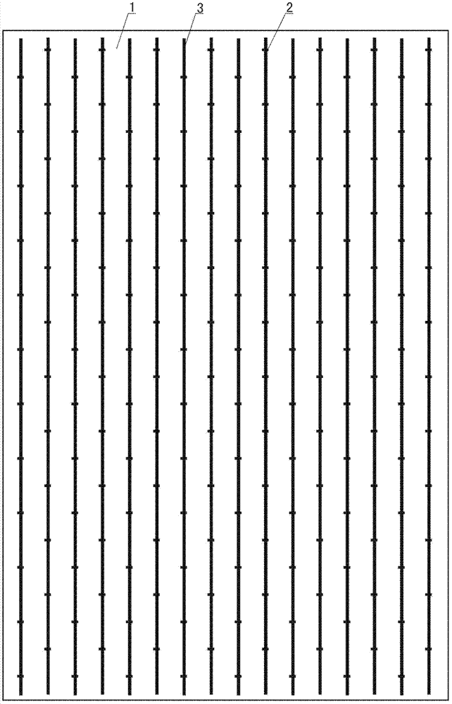
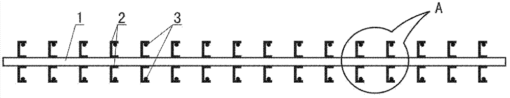
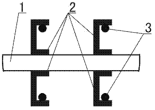
[0023] like figure 1 , figure 2 and image 3 As shown, the present invention comprises rectangular steel plate 1, 匚-shaped drag hook 2 and vertical reinforcing bar 3, with the major axis direction of steel plate 1 being the long side direction as the up and down direction, and the short axis direction of steel plate 1 being the broad side direction as the left and right direction, The front and rear two large planes of the steel plate 1 are respectively welded with a plurality of 匚-shaped pull hooks 2, and the adjacent 匚-shaped pull hooks 2 are welded and installed on the large plane of the steel plate 1 in a quincunx shape, and each 匚-shaped pull hook 2 is formed by itself The plane is perpendicular to the large plane of the steel plate 1, and the plane formed by each 匚-shaped drag hook 2 itself is parallel to the horizontal plane. On the last two large planes, a plurality of vertical steel bars 3 in the up and down direction are welded and installed respectively through t...

Embodiment 2

[0025] like Figure 4 , Figure 5 and Figure 6 As shown, if the steel plate has a large area and a large width in the minor axis direction, it is necessary to install the transverse reinforcement 4 by welding to avoid deformation of the steel plate 1 in the minor axis direction. This structure completely comprises the structure in embodiment 1, promptly comprises rectangular steel plate 1, 匚-shaped drag hook 2 and vertical reinforcing bar 3, and the connection structure between rectangular steel plate 1, 匚-shaped drag hook 2 and vertical reinforcing bar 3 is also identical with embodiment 1, the following structures are added on this basis: the front and rear two large planes of the steel plate 1 are respectively welded and installed with a plurality of horizontal steel bars 4 in the left and right directions through the 匚-shaped pull hook 2, and the multiple horizontal steel bars 4 are evenly tiled Installed on the large plane of the steel plate 1; the distance between adj...


PUM


Abstract

The invention discloses a mounting and fixing device for a steel plate wall. The mounting and fixing device comprises a steel plate, wherein the long axis direction of the steel plate is perpendicular to the short axis direction of the steel plate; a plurality of pull hooks are respectively welded on a front large plane and a back large plane of the steel plate by taking the long axis direction of the steel plate as a longitudinal direction and the short axis direction of the steel plate as a transverse direction; a plane formed by each pull hook is perpendicular to the large planes of the steel plate; a plurality of longitudinal upright steel bars are welded on the front large plane and the back large plane of the steel plate respectively through the pull hooks and are uniformly and flatly arranged on the large planes of the steel plate. According to the mounting and fixing device, the pull hooks are welded on the two planes of the steel plate, and the upright steel bars are connected with one another through the pull hooks, so that the steel plate, the pull hooks and the upright steel bars form a whole; and therefore, the integrated rigidity is improved, the stability of the steel plate wall can be guaranteed, and the steel plate wall can not deform; the pull hooks can also improve the bonding strength between the steel plate wall and concrete, so that casting construction is facilitated; the pull hooks can also replace studs, so that steel materials are saved, and the working efficiency is improved.

Description

technical field [0001] The invention relates to an installation device for a steel plate wall in the field of building construction, in particular to a stable and non-deformable installation and fixing device for a steel plate wall. Background technique [0002] Adding steel plates in the concrete shear wall can effectively improve the shear performance of the wall and increase the bearing capacity of the wall. Because it is installed in the concrete shear wall, as a kind of wall, this kind of steel plate is also called steel plate wall. However, since the steel plate is generally relatively thin, when the width and length are large, it has no stability and is easily deformed, which makes installation more difficult, so it is necessary to weld a strengthening device on the steel plate. Traditional steel plate walls generally need to weld stiffeners on the steel plates or connect I-beams or channel steels to increase the stability of the steel plate walls. However, when usi...

Claims


Application Information

Patent Timeline
Patent Type & Authority Applications(China)
IPC IPC(8): E04C2/38
Inventor 王晓丽李继超柴达董亚兴赵亮贡秀刚王海川
Owner THE SECOND CONSTR ENG CO LTD CCSEB
Why Eureka
Try Eureka