Air-powered rotary-cut type pipeline dredging apparatus

A rotary cutting and pipeline technology, which is used in indoor sanitary pipeline installations, water supply installations, buildings, etc., can solve problems such as low work efficiency, high cost, and airflow loss, achieve good social and economic benefits, and be easy to manufacture or transform. , the effect of improving work efficiency

Inactive Publication Date: 2014-10-15
张弘
View PDF1 Cites 0 Cited by
  • Summary
  • Abstract
  • Description
  • Claims
  • Application Information

AI Technical Summary

Problems solved by technology

[0002] At present, the dredging of urban civil drainage pipes is divided into two types: manual dredging and mechanical equipment dredging. Manual dredging refers to placing steel wire ropes or bamboo strips and other slender tools in the pipeline to dredge the pipeline. The advantage is that it is convenient and not limited by the site. , the disadvantage is that the labor intensity of the workers is high and the efficiency is low
Mechanical equipment dredging is generally divided into two categories: one is the introduction of foreign high-pressure water flushing machinery to dredge the pipeline through the impact of high-pressure water. Its advantage is high efficiency, and its disadvantage is high cost. In addition, when elastic obstacles are encountered in the pipeline , the effect is not ideal; the other is the hose vibration dredging machine, which has the advantages of high efficiency and low cost, and its disadvantage is that the distance of dredging at one time is short and inconvenient to use.
The air compressor is connected to the sequence valve through the inflation pipe, and the reversing valve is respectively connected to the air inlet pipe, the air inlet and return pipe and the pneumatic quick-opening valve. The accumulator is connected to the blocking body through a small-diameter rubber hose, which can dredge various pipelines with high efficiency, but its disadvantages are: complex structure, high manufacturing cost, and pipeline dredging only by air pressure. The effect is not ideal, affecting the use
However, the axial blades of the dredging device directly penetrate the front and rear end fixing plates, causing the airflow ejected from the air nozzle to be lost back and forth, so that the pressure is not very high and the work efficiency is low

Method used


Image

  • Air-powered rotary-cut type pipeline dredging apparatus
  • Air-powered rotary-cut type pipeline dredging apparatus
  • Air-powered rotary-cut type pipeline dredging apparatus

Examples


Embodiment 1

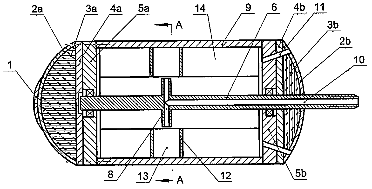
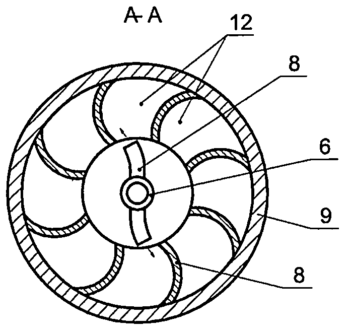
[0035] Embodiment 1: see figure 1 , figure 2 , a pneumatic rotary cutting type pipeline dredging device, including a casing, an air shaft 6, wherein the casing includes a hollow cylinder 9 and fixed plates 5a, 5b fixed at the front and rear ends of the hollow cylinder, and the fixed plates at the front and rear ends 5a, 5b are also respectively fixed with front and rear baffles 4a, 4b on the outer side surfaces, and the sealing covers outside the fixed baffles 4a, 4b at the front and rear ends are positioned at the outside of the front side sealing covers to have a stirring and cutting mechanism 1, and the hollow cylinder 9 A certain number of axial vanes 14 are evenly distributed and fixed on the inner wall, and the air shaft 6 is installed on the front and rear fixing plates 5a, 5b of the casing through bearings, and its rear end passes through the rear fixing plate 5b and connects with the air delivery pipe of the air compressor. connection, the rear part of the air shaft...

Embodiment 2

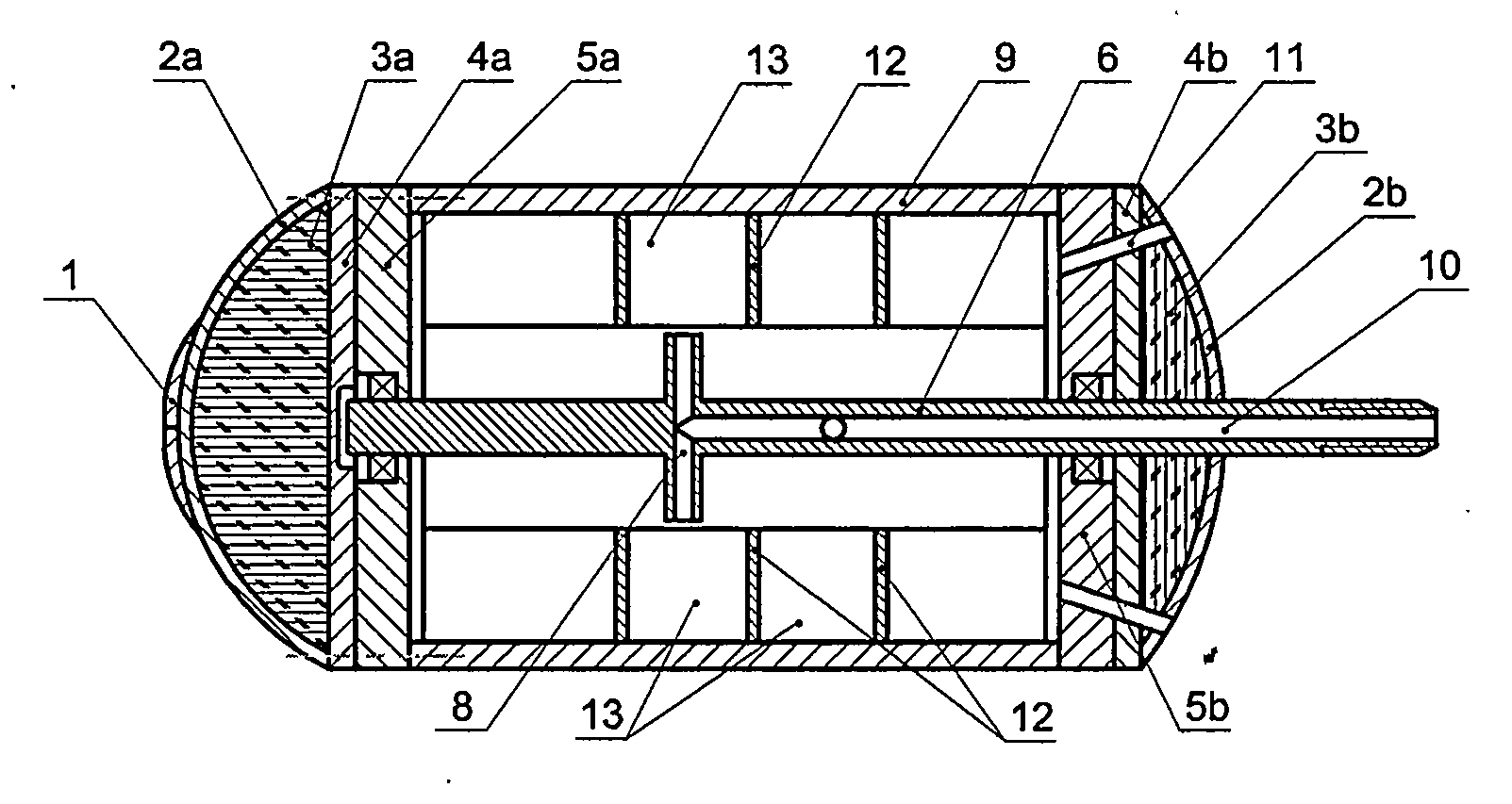
[0041] Example 2: see image 3 , Figure 4 , Figure 5 , Image 6 , Figure 7 , Figure 8-1 , Figure 8-2 , the numbering is the same as in Embodiment 1, the meaning is the same, and the same parts will not be repeated. The difference is that at least two jet surfaces are arranged on the jet pipe, each jet plane is parallel to each other, and each jet surface is provided with at least two jet surfaces. Centrosymmetric jet tube.

[0042] Transverse baffles are respectively fixed on both sides of the opposite axial vanes on each air jet surface, that is, there is a groove-like structure surrounded by front and rear baffles, axial vanes and the inner wall of the hollow cylinder at the corresponding position on each air jet surface.

Embodiment 3

[0043] Embodiment 3: see Figure 9 , Figure 10 , a pneumatic rotary cutting type pipeline dredging device, including a casing, an air shaft 6, wherein the casing includes a hollow cylinder 9 and fixed plates 5a, 5b fixed at the front and rear ends of the hollow cylinder, and the fixed plates at the front and rear ends 5a, 5b are also fixed with front and rear baffles 4a, 4b respectively on the outer side surfaces, and the sealing covers outside the fixed baffles 4a, 4b at the front and rear ends are positioned at the outside of the front side sealing covers to have a stirring and cutting mechanism 1, and the air shaft 6 passes through the bearings. Installed on the front and rear fixing plates 4a and 4b of the casing, the rear end of which passes through the rear fixing plate 4b and is connected with the air delivery pipe of the air compressor, the rear part of the air shaft 6 is a hollow structure and an air injection pipe 8 is arranged on it , the inner end of the jet pipe...


PUM


Abstract

The invention discloses an air-powered rotary-cut type pipeline dredging apparatus. A casing of the apparatus includes a front mounting plate, a rear mounting plate, a hollow cylinder and blades; a plurality of blades in axial direction are uniformly distributed on the inner wall of the hollow cylinder, and two ends of each blade are respectively fixedly connected with the front mounting plate and the rear mounting plate; an air shaft is installed on the front and the rear mounting plates via a bearing, and the rear end of the air shaft penetrates the rear mounting plate and is connected with a gas pipe of a compressor; the air shaft with a hollow rear portion is provided wtih a plurality of gas nozzles communicating with a central axis hole of the air shaft in inner end, while the outer end of each gas nozzle corresponding to blades; high pressure airflow blows onto the blades to drive the casing rotating around the air shaft; a front end cover and a rear end cover are respectively outside provided the front mounting plate and the rear mounting plate; and an agitating cutting mechanism is installed on the outer surface of the front end cover, and the rear end cover is uniformly provided with a plurality of inclined exhaust pipes to exhaust air uniformly to rear upward side. The air-powered rotary-cut type pipeline dredging apparatus has the simple structure, good dredging effect, relatively high efficiency and relatively good economic benefit.

Description

Technical field: [0001] The invention relates to a pipeline dredging machine, in particular to a pneumatic rotary cutting type pipeline dredging device. Background technique: [0002] At present, the dredging of urban civil drainage pipes is divided into two types: manual dredging and mechanical equipment dredging. Manual dredging refers to placing steel wire ropes or bamboo strips and other slender tools in the pipeline to dredge the pipeline. The advantage is that it is convenient and not limited by the site. , the disadvantage is that the labor intensity of the workers is high and the efficiency is low. Mechanical equipment dredging is generally divided into two categories: one is the introduction of foreign high-pressure water flushing machinery to dredge the pipeline through the impact of high-pressure water. Its advantage is high efficiency, and its disadvantage is high cost. In addition, when elastic obstacles are encountered in the pipeline , the effect is not ideal...

Claims


Application Information

Patent Timeline
IPC IPC(8): E03C1/30
Inventor 张弘
Owner 张弘
Why Eureka
Try Eureka