fuel supply system

A fuel supply system and fuel technology, which are applied in charging systems, fuel injection devices, liquid fuel feeders, etc., can solve the problems of difficult components, complex structures, and generation of sealing points, and achieve improved accessibility and reduced quantity. , the effect of structure simplification

Inactive Publication Date: 2018-12-11
MAN ENERGY SOLUTIONS SA
View PDF8 Cites 0 Cited by
  • Summary
  • Abstract
  • Description
  • Claims
  • Application Information

AI Technical Summary

Problems solved by technology

[0004] The piping connection of the pressure limiting valve 13 and the flushing valve 14 to the pressure accumulator unit 9 via the high pressure lines 15 , 16 is disadvantageous because additional sealing points are created due to this
In addition, the piping connection of the above-mentioned components of the fuel supply system results in a structurally complex fuel supply system requiring a lot of installation space
Access to individual components of the fuel supply system is more difficult due to pipe connections

Method used


Image

  • fuel supply system
  • fuel supply system

Examples


Embodiment Construction

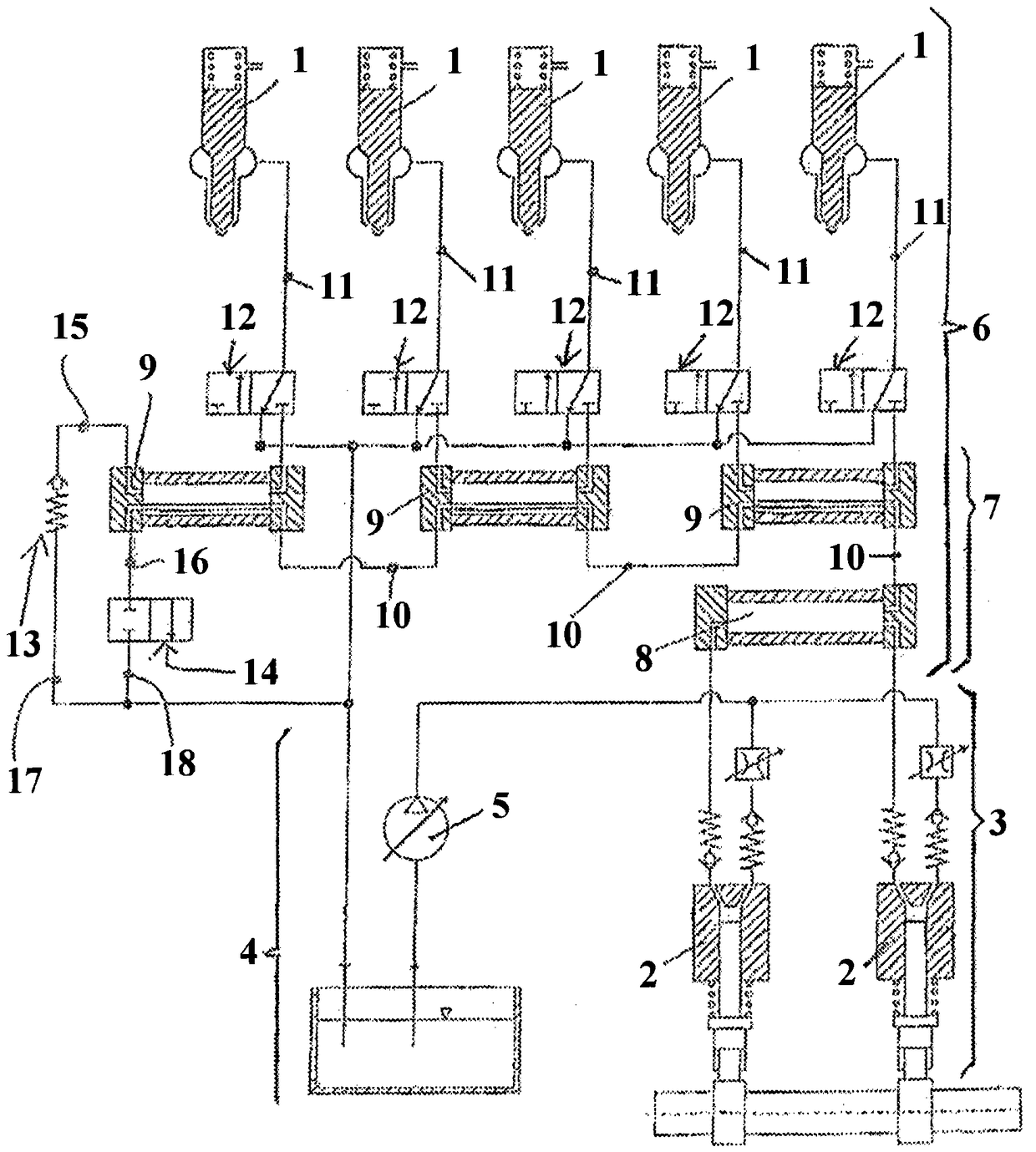
[0042] The invention relates to a fuel supply system for an internal combustion engine, especially a common rail fuel supply system, especially designed as a large diesel engine or a marine diesel engine. The basic structure of this fuel supply system has been referred to figure 1 to describe.

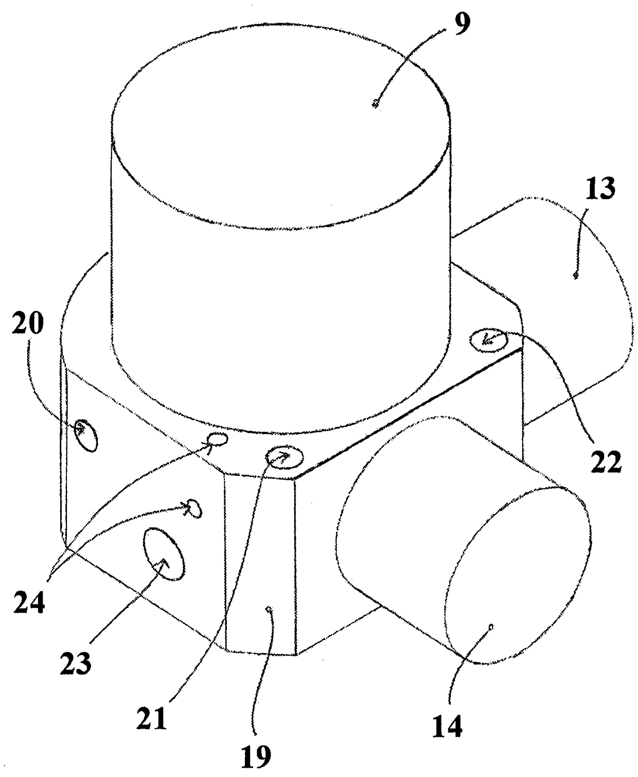
[0043] The invention concerns the details of the fuel supply system by means of which, in the area of ​​the pressure accumulator 9 interacting with the pressure limiting valve 13 and the flushing valve 14 , the plumbing work can be reduced. For details on this, refer to the following figure 2 to describe.

[0044] therefore, figure 2 Assignment of a valve block 19 to the pressure accumulator unit 9 interacting with the pressure limiting valve 13 and the flushing valve 14 is shown, wherein the pressure accumulator unit 9 acts directly on the valve block 19 , wherein the valve block 19 also accommodates or carries the pressure limiting valve 13 and flush valve 14.

[0045] Further...


PUM


Abstract

PROBLEM TO BE SOLVED: To provide a new fuel supply device for an internal combustion engine in which individual component of the fuel supply device has high improved accessibility, and provide a construction constituted by a storage unit, a pressure relief valve, and a cleaning valve of the fuel supply device.SOLUTION: A storage unit (9) in which the storage unit, a pressure relief valve, and a cleaning valve cooperate together is provided with a valve block. The valve block is directly mounted to the storage unit (9), and accommodates the pressure relief valve (13) and the cleaning valve (14).

Description

technical field [0001] The invention relates to a fuel supply system for an internal combustion engine. The invention also relates to the assembly of a pressure accumulator unit, a pressure limiting valve and a flushing valve of such a fuel supply system. Background technique [0002] figure 1 The basic configuration of a common rail fuel supply system for an internal combustion engine known in the prior art is shown. Such a construction is known from DE 101 57 135 B4. therefore, figure 1 The common rail fuel supply system comprises at least one injector 1 each for each cylinder of the internal combustion engine. Fuel can be injected into the individual cylinders of the internal combustion engine via the injector 1 . The common rail fuel supply system also includes a pumping device 3 comprising at least one low-pressure pump 5, at least one high-pressure pump 2 and a high-pressure pump accumulator unit 8 to deliver fuel from the low-pressure zone 4 of the common-rail fu...

Claims


Application Information

Patent Timeline
Patent Type & Authority Patents(China)
IPC IPC(8): F02M63/00
CPCF02M55/025F02M63/0012F16K17/04F02M21/10F02M37/0023F02M37/007F02M63/0007F02M63/0049F02M63/005F02M63/0052F02M63/027F02M63/029F02M2200/247F02M2200/248Y02T10/30F02M37/00F02M63/00F02M63/0275
Inventor W·瓦格纳R·施特罗贝尔
Owner MAN ENERGY SOLUTIONS SA
Why Eureka
Try Eureka