Use of a motor-driven speed-variable hydraulic pump as a hydrostatic transmission

A technology of hydraulic pumps and motors, which is applied in the field of application of motor-driven, variable-speed hydraulic pumps as hydrostatic transmissions, and can solve the problems of expensive energy consumption of hydraulic machines, etc.

Active Publication Date: 2014-10-15
ROBERT BOSCH GMBH
View PDF9 Cites 3 Cited by
  • Summary
  • Abstract
  • Description
  • Claims
  • Application Information

AI Technical Summary

Problems solved by technology

The hydraulic accumulator or hydraulic accumulator on the one hand makes the hydraulic machine expensive and on the other hand has a not insignificant influence on the level of energy consumption of the hydraulic machine for this purpose

Method used


Image

  • Use of a motor-driven speed-variable hydraulic pump as a hydrostatic transmission
  • Use of a motor-driven speed-variable hydraulic pump as a hydrostatic transmission
  • Use of a motor-driven speed-variable hydraulic pump as a hydrostatic transmission

Examples


Embodiment approach

[0047] A) a transmission with two different shifting stages (minimum and maximum pump displacement);

[0048] B) As a continuously variable automatic transmission with continuous adjustment of the transmission ratio.

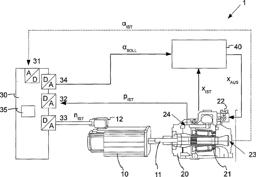
[0049] According to the third embodiment, it can also be arranged like this: if it is not necessary to adjust the actual swing angle α of the swing plate 10 of the hydraulic pump 10 IST Input into the regulating device 30 , the input 34 of the regulating device 30 is then omitted. In this case, the swivel angle sensor 23 can also be omitted. As a result, it is also not necessary to connect the pivot angle sensor 23 to the adjusting device 30 . As a result, adjustment device 30 can also be realized more cost-effectively. In other respects, the second exemplary embodiment is designed identically to the first exemplary embodiment.

[0050] In summary, in the previously described exemplary embodiment, an adjusting device 30 and an adjusting method for adjusting ...


PUM


Abstract

Provided are an adjusting device (30) and an adjusting method for adjusting a motor (10) driven hydraulic pump (20). The adjusting device (30) comprises an adjusting mechanism (35) for adjusting the speed (n) and the stroke volume (VH) of the hydraulic pump (20) for regulating the pressure of the hydraulic pump (20) or the force control or position control of a hydraulic cylinder. Here, the stroke volume (Vh) of the hydraulic pump (20) is either stationary by adjusting the angle ([alpha]) of the hydraulic pump (20) or dynamically adjusted by dynamically adjusting the swivel angle ([alpha]) of the hydraulic pump (20) and the speed (n) of the motor (10) in normal operation. The unit consisting of the hydraulic pump (20), the motor (10) and the drive controller or adjusting device (30) is thereby used as an electro-hydraulic transmission for optimizing the system efficiency.

Description

technical field [0001] The invention relates to a regulating device and a regulating method for regulating a motor-driven, variable-speed hydraulic pump, wherein the motor-pump unit is used as a hydraulic pump with variable and adaptive correction. (nachgeführt) A transmission with a transmission ratio. The transmission ratio is defined here as a function of the operating point and the optimization target, in particular power, energy efficiency, etc., and is set automatically by the system. Background technique [0002] Variable speed hydraulic presses are used in many technical applications. In general, a high positioning accuracy of the hydraulic press and a minimum energy consumption are required here. Furthermore, above all in a quiet working environment, a low noise pollution caused by the hydraulic press is often predetermined, so that the noise load on the environment is kept as low as possible. [0003] The problem here is that sufficient power should be obtained ...

Claims


Application Information

Patent Timeline
Patent Type & Authority Applications(China)
IPC IPC(8): F04B49/06
CPCF04B1/324F04B2201/1201F04B49/06F04B49/065F04B2201/0206
Inventor M.瓦勒
Owner ROBERT BOSCH GMBH
Why Eureka
Try Eureka