

Bionic impeller for exhaust hood
A technology for range hoods and range hoods is applied in the fields of removing range hoods, applications, and household stoves, etc., and can solve the problems of reducing the shedding frequency of vortex shedding of leading edge pressure impacting trailing edge, reducing the working efficiency of fans, increasing motor load, etc., so as to reduce tailing Fringe vortex shedding frequency, easy processing, and the effect of reducing motor load
- Summary
- Abstract
- Description
- Claims
- Application Information
AI Technical Summary
Problems solved by technology
Method used
Image

Examples
Embodiment 1
[0022] The bionic impeller in this example is an improvement based on the prototype impeller, and the parameters of the prototype impeller are listed in Table 1:
[0023] Structural parameters symbol size Impeller inner diameter D 1 216mm Impeller outer diameter D 2 252mm Impeller width B 136mm number of blades Z 60 blade thickness d 0.4mm Import mounting angle β 1 72° outlet mounting angle β 2 168° blade curvature radius R 13.6mm
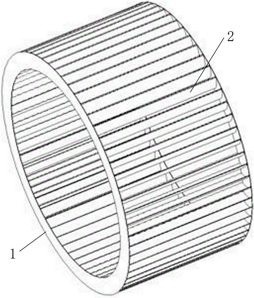
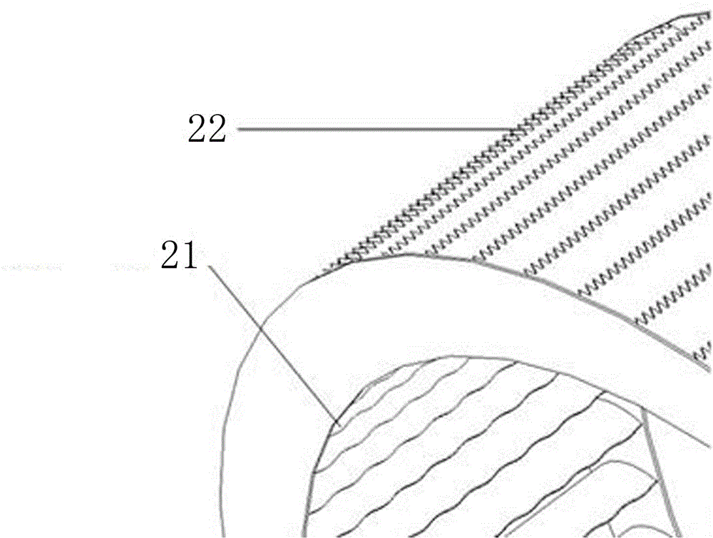
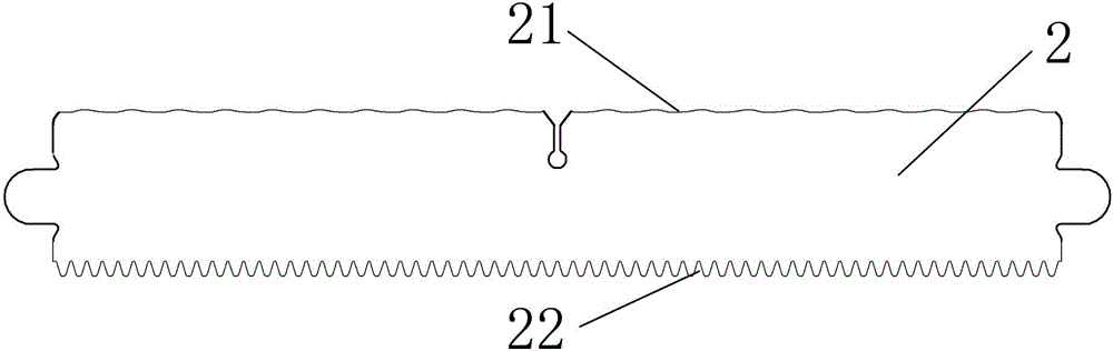
[0024] see Figure 1-6 , this embodiment includes two sets of annular end surfaces and blades, and blades are uniformly connected between the two sets of annular end surfaces. The blades in this embodiment are bionic blades, and the impeller blades are uniformly arranged with a single type of bionic blades. The side is the front edge of the wave structure, and the side facing the impeller range hood is the trailing edge of the sawtooth structure:
[0025] The leadin...
PUM
 Abstract
Description
Claims
Application Information