Fin evaporator and electric refrigerator adopting fin evaporator

A technology of finned evaporators and evaporators, applied in evaporators/condensers, refrigeration components, refrigerators, etc. Poor thermal efficiency and other problems, to avoid the reduction of cooling capacity, insufficient heat transfer, and avoid uneven frosting

Inactive Publication Date: 2014-10-15
孙卫华
View PDF7 Cites 3 Cited by
  • Summary
  • Abstract
  • Description
  • Claims
  • Application Information

AI Technical Summary

Problems solved by technology

Due to the large temperature difference between the refrigerant inlet section and the outlet section, the cooling capacity of the refrigerant inlet section will be directly transferred to the outlet section through the fins, which will cause internal loss of cooling capacity and decrease in cooling capacity.
The high-temperature section of the evaporator tube is directly connected to the low-temperature section through fins, which will also cause the cooling capacity of the low-temperature section to be directly transferred to the high-temperature section through the fins, resulting in internal loss of cooling capacity and a decrease in cooling capacity.
Because the temperature of the refrigerant inlet section is low, the frosting speed is fast, and the temperature of the refrigerant outlet section is high, and the frosting speed is slow. Poor; in the refrigerant outlet section, the frost layer is thin, the resistance is small, and the wind speed is high, and the wind tends to flow through the low temperature area of ​​the refrigerant outlet section, resulting in reduced heat transfer effect
Since the refrigerant absorbs heat from the inlet to the outlet of the evaporator, the temperature gradually rises, and the temperature distribution of some pipes increases with the flow direction of the wind. This is a downstream heat transfer method, and the heat transfer effect is poor.

Method used


Image

  • Fin evaporator and electric refrigerator adopting fin evaporator
  • Fin evaporator and electric refrigerator adopting fin evaporator
  • Fin evaporator and electric refrigerator adopting fin evaporator

Examples


Embodiment 1

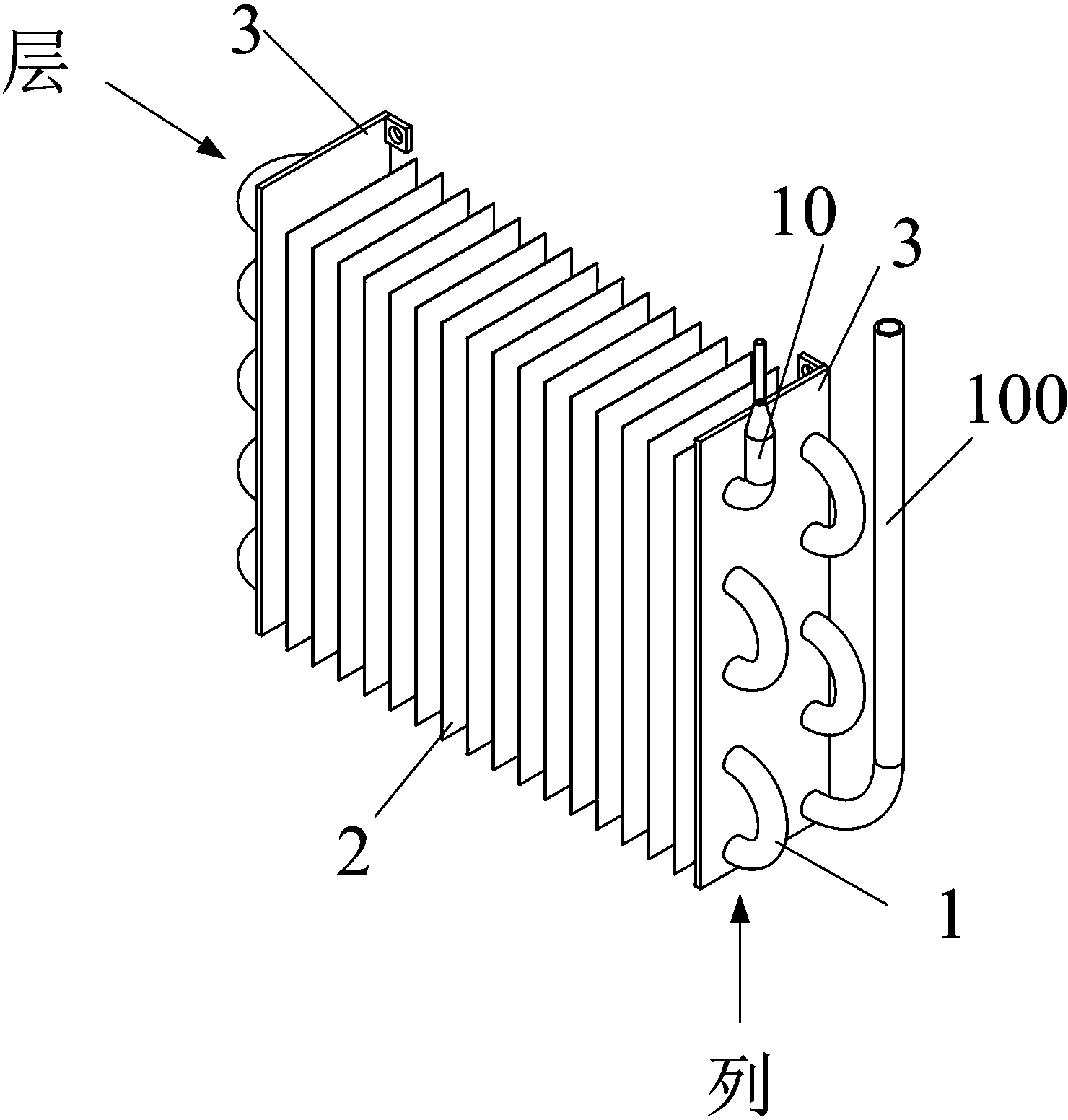
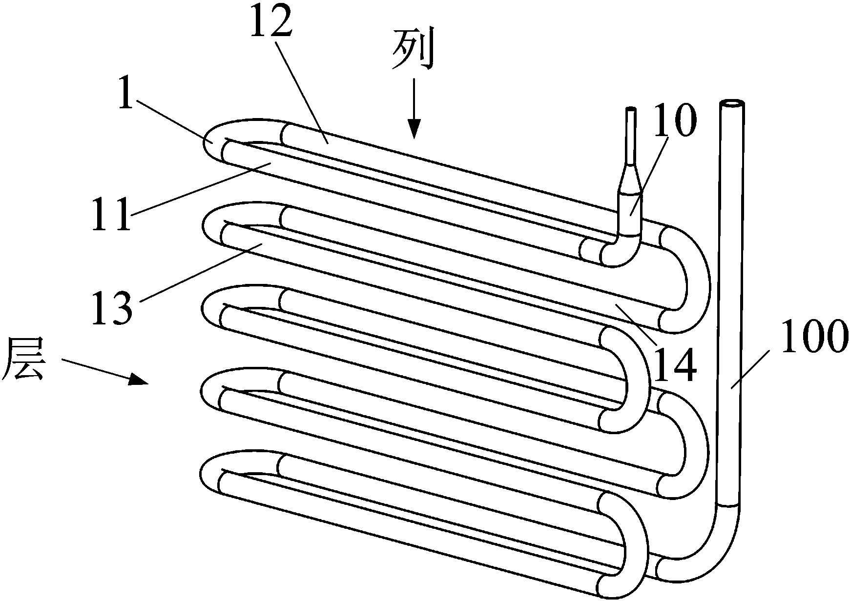
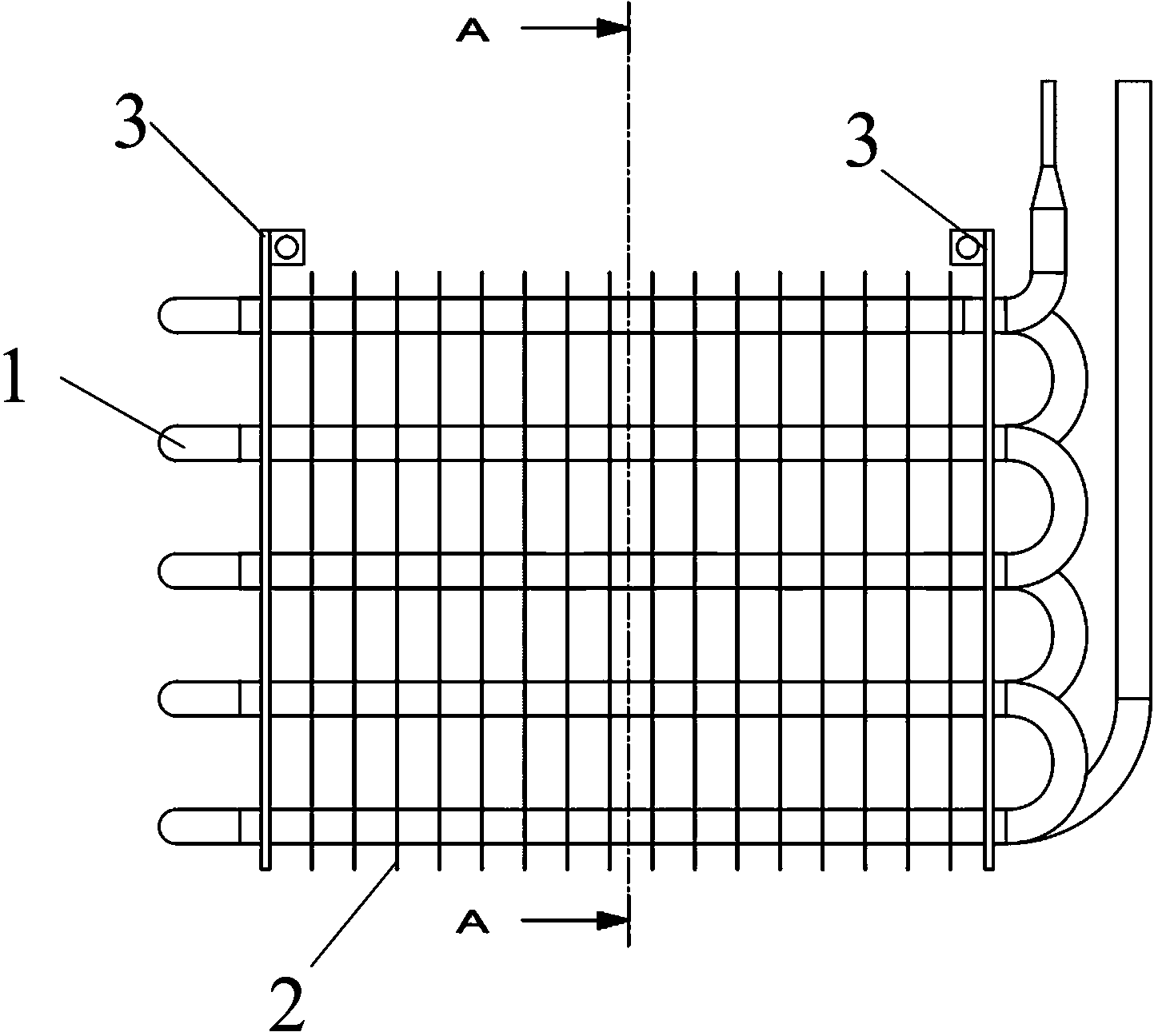
[0036] like figure 1 , 2 , Shown in 3 and 4 is to invent a kind of installation structure of evaporator. Including evaporation tube 1, fins 2, fixed plate 3. The fixing plate 3 plays a role of fixing the evaporation tube 1 at the left and right ends, and the fixing effect of the evaporator. The evaporating tube 1 passes through the fins 2 and the fixed plate 3, increasing the heat exchange area.

[0037] The temperature at the inlet end 10 of the evaporator tube is relatively low, and the temperature at the outlet end 100 of the evaporator tube is relatively high. During the installation, direct heat conduction between the evaporator outlet section and the evaporator outlet section through the fins is firstly avoided. In the first layer, enter the first row of evaporation tubes 11 from the evaporator inlet port 10, the first layer of the first row of evaporation tubes 11 is connected to the first layer of the second row of evaporation tubes 12 through the elbow, the evapora...

Embodiment 2

[0042] like Figure 5 , 6 , Shown in 7 and 8 is to invent a kind of installation structure of evaporator. The difference between this example and Example 1 is that the distance between layers is slightly smaller, and the layers are staggered. 13 The connecting line is perpendicular to the layer. In Example 2, the line connecting the first row of evaporating tubes 11 on the first layer and the first row of evaporating tubes 13 on the second layer faces the layer at an angle of 60 degrees.

[0043] The advantage of this example is that while maintaining the diameter of the connecting elbow of the evaporating tube 1, the distance between layers is reduced, so that the number of layers arranged in the same height is increased.

Embodiment 3

[0045] like Figure 9 , 10 , Shown in 11 and 12 is to invent a kind of installation structure of evaporator. The difference between this example and the second example is that there are three rows of evaporation tubes 1 , that is, each layer is increased from two evaporation tubes 1 to three evaporation tubes 1 .


PUM


Abstract

The invention relates to the technical field of an electric refrigerator in household appliances, in particular to a fin evaporator, which comprises a fixing plate, two lines or a plurality of lines of evaporation pipes and a plurality of fins, wherein the evaporation pipes are arranged on the fixing plate, the fins are sheathed on the evaporation pipes, and the evaporation pipes enter the evaporator from the top layer, spirally go downwards in a snake shape at each layer, and are sent out of the evaporator at the bottom layer. The air supply direction is upward from the bottom, the flowing direction of refrigerants in a pipeline is generally opposite to the air supply direction, through adopting the convection mode, the heat exchange is enhanced, and the cooling capacity transfer efficiency is improved. The refrigerant pipeline direction is integrally downward from the top, and the distance between an inlet section and an outlet section of each evaporation pipe reaches the maximum value. The temperature differences of the inlet section and the outlet section of each evaporation pipe are great, the heat exchange of the traditional evaporator through the fins since the inlet section and the outlet section of the evaporation pipe are adjacent is avoided, i.e., the cooling capacity grade reduction is avoided, and the cooling capacity utilization rate is improved. The frosting non-uniformity of the fins on the air supply cross section of the traditional evaporator, and the air supply non-uniformity and the heat exchange efficiency reduction due to the frosting non-uniformity are avoided.

Description

technical field [0001] The invention relates to a refrigeration system, which is suitable for evaporators in commercial refrigerators and refrigerators, especially finned evaporators. Background technique [0002] A refrigerator refrigeration system generally includes a compressor, an evaporator, a capillary tube, a condenser, and a refrigerant. The refrigerant is compressed by the compressor to become a high-temperature and high-pressure gas, and releases heat in the condenser to become a high-pressure liquid. It enters the evaporator through the capillary tube to vaporize and absorb heat, and the vaporized and overheated refrigerant returns to the compressor. The evaporator is a heat exchange device, and the refrigerant evaporates in the evaporator to increase the temperature and transfer the cold energy to the refrigerator compartment. [0003] At present, finned evaporators are used in air-cooled refrigerators. The inlet section of the refrigerant evaporator coil is dir...

Claims


Application Information

Patent Timeline
Patent Type & Authority Applications(China)
IPC IPC(8): F25B39/02
Inventor 孙卫华
Owner 孙卫华
Why Eureka
Try Eureka