Automatic ultrasonic flaw detector

A technology of ultrasonic and flaw detector, which is applied in the analysis of solids by sound wave/ultrasonic wave/infrasonic wave, material analysis by sound wave/ultrasonic wave/infrasonic wave, instruments, etc. , unable to automatically spray the couplant and other problems, to achieve the effect of compact structure, low requirements and easy assembly

Inactive Publication Date: 2014-10-15
JILIN UNIV
View PDF7 Cites 22 Cited by
  • Summary
  • Abstract
  • Description
  • Claims
  • Application Information

AI Technical Summary

Problems solved by technology

[0004] The technical problem to be solved by the present invention is to overcome the problems that the existing ultrasonic flaw detection equipment cannot automatically spray the coupling agent, the probe cannot move automatically, the probe positioning accuracy is low, the surface shape of the sample is high, and it is difficult to realize the three-dimensional and automatic flaw detection. An automatic ultrasonic flaw detector is provided

Method used


Image

  • Automatic ultrasonic flaw detector
  • Automatic ultrasonic flaw detector
  • Automatic ultrasonic flaw detector

Examples


Embodiment 1

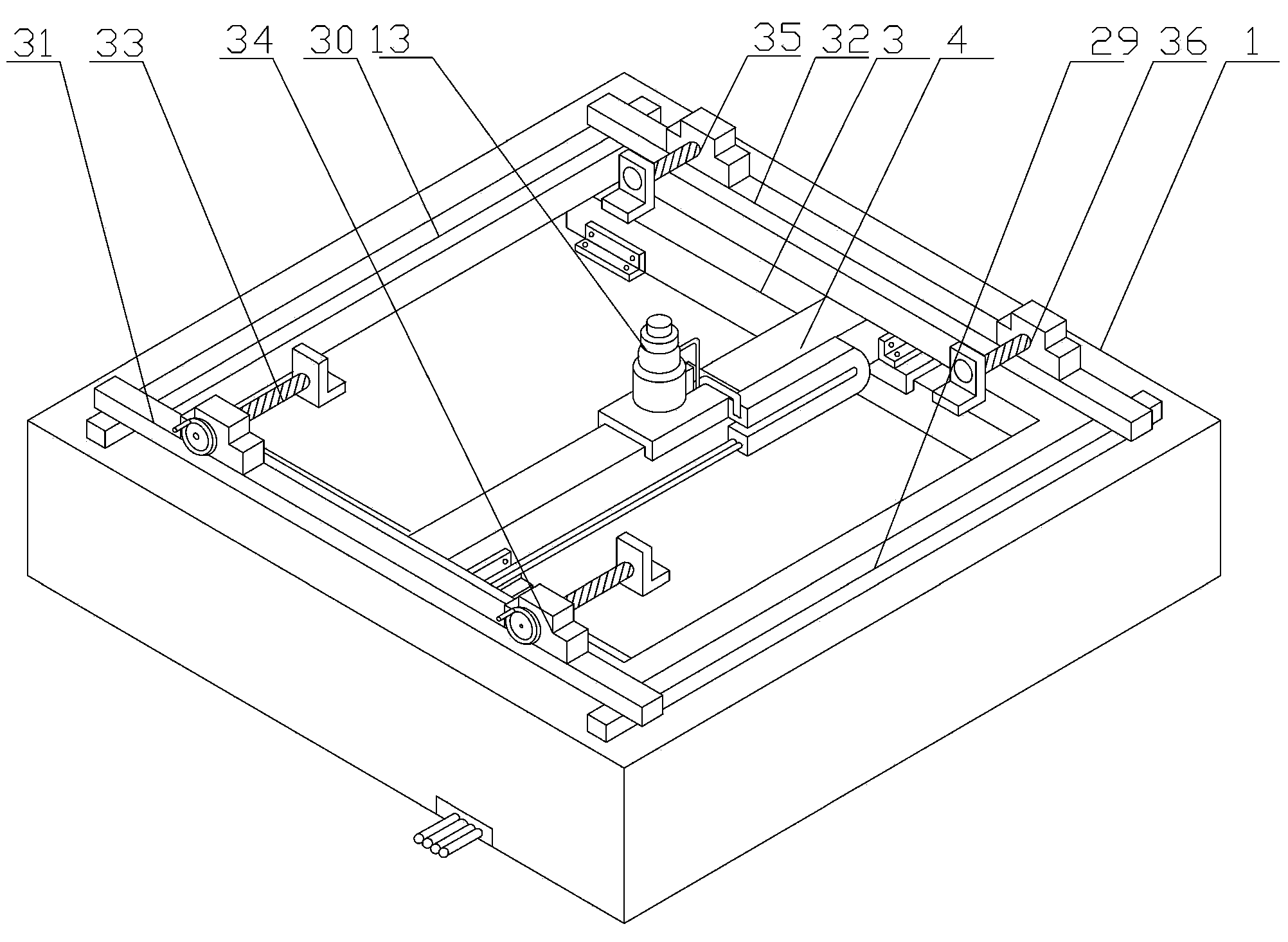
[0045] refer to figure 1 An automatic ultrasonic flaw detector includes a guide rail part, a fixture part, a probe part, a data transmitting and receiving circuit part and a data processing part.

[0046] The probe part is installed on the top surface of the slide block of the transverse guide rail 4 in the guide rail part through its probe lifting frame 16 and is fixedly connected by bolts, and the probe part extends from the square through hole on the cover in the guide rail housing 1 in the guide rail part. It can be seen that the probe part is connected with the wires of the data transmitting and receiving circuit part, the data transmitting and receiving circuit part is connected with the data processing part of the wires, and the fixture part is installed on the top cover of the guide rail housing 1 in the guide rail part.

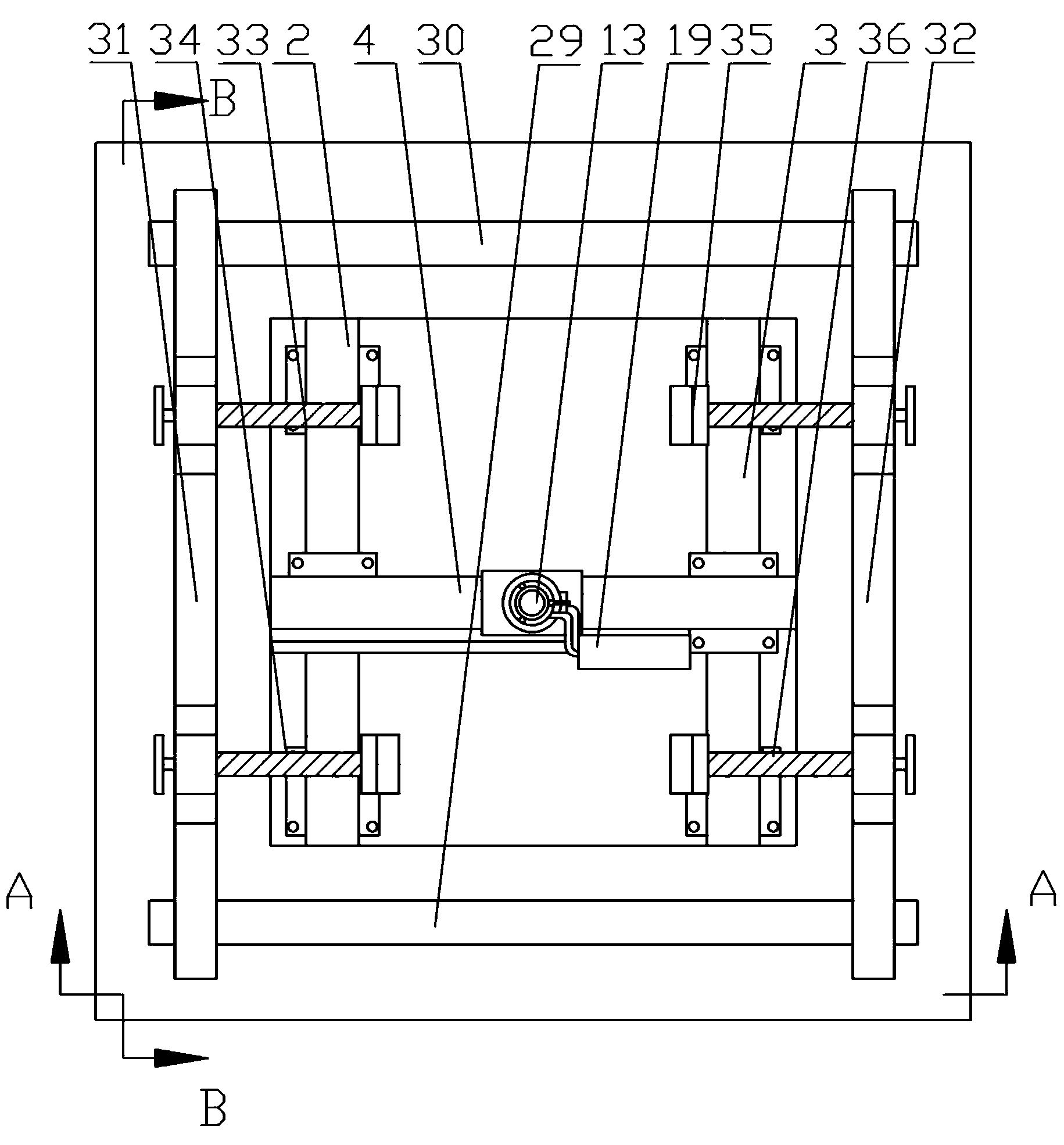
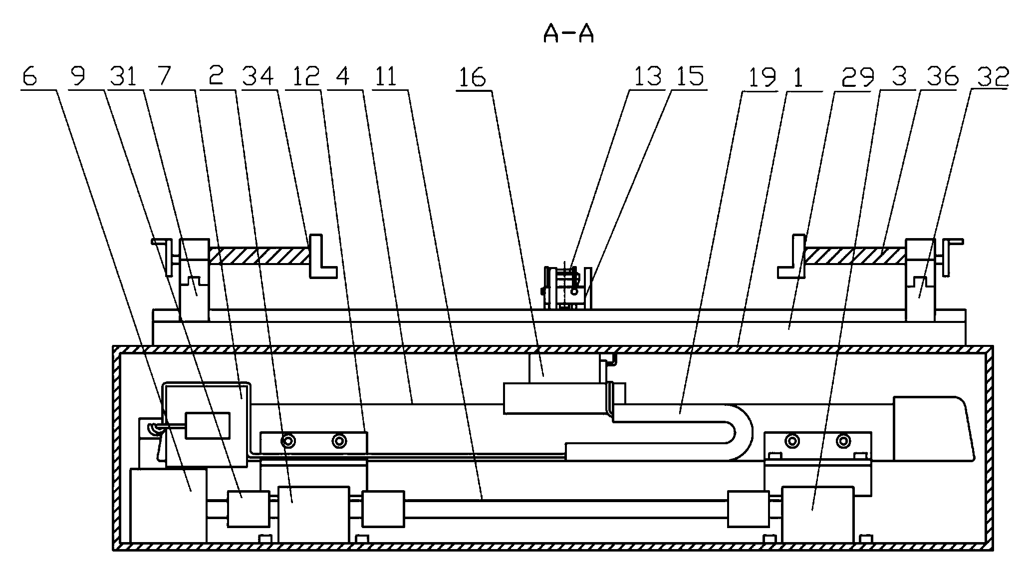
[0047] refer to Figure 2 to Figure 4 , the guide rail part includes a guide rail housing 1, a longitudinal No. 1 guide rail 2, a longitudinal No. ...

Embodiment 2

[0085] refer to Figure 5 , an automatic ultrasonic flaw detector, comprising a guide rail part, a jig part, a probe part, a data transmitting and receiving circuit part and a data processing part, the probe part is installed on the slide block of the transverse guide rail 4 in the guide rail part through its probe lifting frame 16 The top surface is fixedly connected by bolts, the probe part protrudes from the square through hole on the cover of the guide rail shell 1 in the guide rail part, the probe part is connected with the data transmitting and receiving circuit part by wires, and the data transmitting and receiving circuit part is connected with the data processing Part of the wires are connected, and the clamp part is installed on the top cover of the guide rail housing 1 in the guide rail part.

[0086] refer to Figure 6 to Figure 8 The guide rail part of the second embodiment of the automatic ultrasonic flaw detector according to the present invention includes a gu...


PUM

PropertyMeasurementUnit
radiusaaaaaaaaaa

Abstract

The invention discloses an automatic ultrasonic flaw detector and aims at overcoming the problem that the existing device probe is incapable of moving automatically so that three-dimensional and automatic flaw detection is difficult to realize. A first longitudinal guide rail and a second longitudinal guide rail of the guide rail part of the automatic ultrasonic flaw detector are fixed in parallel at the two sides of the bottom panel of a guide rail shell in the longitudinal direction; the two ends of a transverse guide rail are fixedly on the sliders of the first longitudinal guide rail and the second longitudinal guide rail, respectively, and the transverse guide rail is perpendicular to the direction of the first longitudinal guide rail; the probe part of the automatic ultrasonic flaw detector is fixed on the slider of the transverse guide rail and electrically connected with a data transmitting/receiving circuit part; the transverse front slide rail and the transverse rear slide rail of a fixture part are mounted in parallel on the guide rail shell, a longitudinal left slide rail and a longitudinal right slide rail are mounted in parallel on the transverse front slide rail and the transverse rear slide rail, a first clamp and a second clamp are mounted on the longitudinal left slide rail, a third clamp and a fourth clamp are mounted on the longitudinal right slide rail; the data transmitting/receiving circuit part is electrically connected with a data processing part.

Description

technical field [0001] The invention relates to a metal test piece and parts quality testing equipment, more precisely, the invention relates to an automatic ultrasonic flaw detector. Background technique [0002] In recent years, many different techniques have been developed for 3D ultrasound imaging. In view of the acquisition methods, four categories can be distinguished: 2D transducer arrays, mechanical scanners, and freehand scanning methods with and without position information. In the medical field, three-dimensional ultrasonic diagnostic equipment has developed rapidly. Ultrasound is a low-cost solution for obtaining stereo imaging compared to CT and MRI imaging. In addition, operation requires no specialized training and no radiation protection. Due to the different shapes of the human body, the ultrasonic instruments used in the medical field are generally controlled manually, which is not suitable for the inspection of large quantities of industrial parts. Thro...

Claims


Application Information

Patent Timeline
Patent Type & Authority Applications(China)
IPC IPC(8): G01N29/04G01N29/265
Inventor 姜巍曹占义孙旭刘勇兵
Owner JILIN UNIV
Why Eureka
Try Eureka