
Energy storage device applied to workover rig

A technology of energy storage device and workover rig, which is applied in the direction of electric energy storage system, electrical components, AC network load balance, etc., and can solve the problems of high power supply quality and reliability, low working efficiency of diesel generator sets, and workover rig Improve workover efficiency and power grid stability, simple installation, and small size to solve problems such as increased operating costs

Inactive Publication Date: 2014-10-15
BEIJING CHNDRIVE ELECTRIC TECH
View PDF5 Cites 1 Cited by
  • Summary
  • Abstract
  • Description
  • Claims
  • Application Information

AI Technical Summary

Problems solved by technology

[0003] The inventor has found in practice that: 1. When using a diesel generator set, the working efficiency of the diesel generator set is low, and there is a waste of energy, which increases the operating cost of the workover rig; The site is usually relatively remote (such as close to the countryside), the demand for electric energy is large, and the requirements for power supply quality and reliability are also high, and the power grid capacity in remote areas is limited, so it may cause certain troubles to the operation of the workover rig

Method used

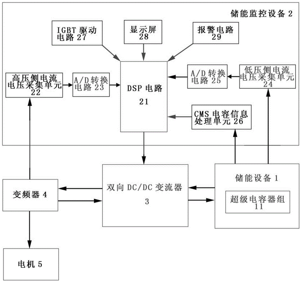
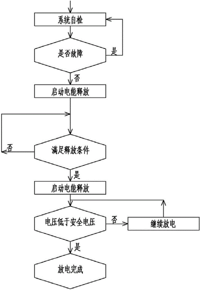
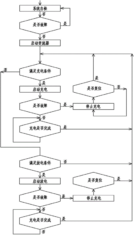

Image

  • Energy storage device applied to workover rig
  • Energy storage device applied to workover rig
  • Energy storage device applied to workover rig

Examples


Embodiment Construction

[0037] In order to further explain the technical means and effects of the present invention to achieve the intended purpose of the invention, the specific implementation methods and methods of the energy storage device applied to the workover rig proposed according to the present invention will be described below in conjunction with the accompanying drawings and preferred embodiments. , features and their effects are described in detail below.

[0038] The core design idea of ​​the present invention is that during the operation of the workover rig, the traveling block decelerates and lowers the stage, charges the energy storage device, and lifts the stage, discharges the energy storage device, and releases the electric energy stored in the energy storage device to the frequency conversion The device provides electric energy for the workover rig. The invention makes full use of the deceleration and lowering stages of the operation process to charge the energy storage device, jud...


PUM


Abstract

The invention relates to an energy storage device applied to a workover rig. The energy storage device comprises energy storage equipment, energy storage monitoring equipment and a two-way DC / DC (Direct Current / Direct Current) converter, wherein the energy storage equipment is connected with the energy storage monitoring equipment and the two-way DC / DC converter respectively; the energy storage monitoring equipment is connected with the two-way DC / DC converter; the two-way DC / DC converter is connected with a DC bus side of a frequency converter and the energy storage equipment respectively; the DC bus side of the frequency converter is connected with a motor, the energy storage monitoring equipment and the two-way DC / DC converter respectively; the energy storage equipment comprises a supercapacitor bank; and the energy storage monitoring equipment comprises a DSP (Digital Signal Processor) circuit, a high-voltage side current and voltage acquisition unit, a low-voltage side current and voltage acquisition unit, A / D (Analog to Digital) conversion circuits, a CMS (Content Management System) capacitance information processing unit, an IGBT (Insulated Gate Bipolar Transistor) driving circuit, a display screen and an alarm circuit. The energy storage device can judge a load and the power supply capacity under the current operation condition in real time, charges the energy storage equipment by fully using deceleration and lowering stages during an operation course, and improves the operation efficiency.

Description

technical field [0001] The invention relates to an energy storage device on a workover rig, in particular to an energy storage device applied to a workover rig powered by a diesel generator set or a power grid (such as a vehicle-mounted workover rig). Background technique [0002] The workover rig is an indispensable maintenance and construction equipment to ensure the normal operation of various types of wells such as oil wells, gas wells or water wells. Current workover rigs generally use diesel generator sets or power grids (commercial power grids) to provide power for them. [0003] The inventor has found in practice that: 1. When using a diesel generator set, the working efficiency of the diesel generator set is low, and there is a waste of energy, which increases the operating cost of the workover rig; The site is usually relatively remote (such as close to the countryside), the demand for electric energy is large, and the requirements for power supply quality and rel...

Claims


Application Information

Patent Timeline
Patent Type & Authority Applications(China)
IPC IPC(8): H02J15/00H02J3/28
Inventor 张正辉朱文琪张超平高贺郑永利赵建平
Owner BEIJING CHNDRIVE ELECTRIC TECH
Learn More