Drilling and rolling combination cutter disc structure for TBM (tunnel boring machine)

A technology of cutter head and hob, which is used in earth-moving drilling, mining equipment, tunnels, etc., can solve the problems of small excavation area, large torque, low rock breaking efficiency, etc., and achieve high rock breaking efficiency and large rocks. The effect of improving the excavation area and driving efficiency

Inactive Publication Date: 2014-10-22
LUOYANG INST OF SCI & TECH
View PDF7 Cites 10 Cited by
  • Summary
  • Abstract
  • Description
  • Claims
  • Application Information

AI Technical Summary

Problems solved by technology

The commonly used cutter head is a planar structure, the excavation area is small, the number of disc-shaped hobs on the cutter head is small, and the rock-breaking efficiency is low, and the rock can only be cut and broken by the cutter head and the disc-shaped hob. Therefore, , the disc-shaped hob is subjected to a large torque during this process, which is easy to wear and has a short service life

Method used


Image

  • Drilling and rolling combination cutter disc structure for TBM (tunnel boring machine)
  • Drilling and rolling combination cutter disc structure for TBM (tunnel boring machine)
  • Drilling and rolling combination cutter disc structure for TBM (tunnel boring machine)

Examples


Embodiment 1

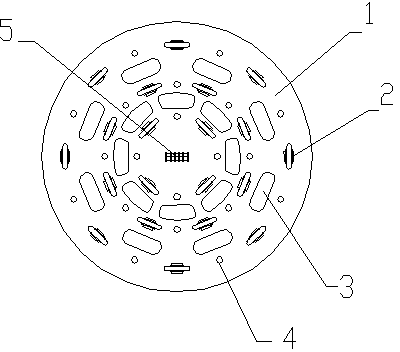
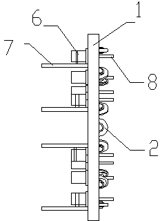
[0018] Embodiment 1: As shown in the figure, a drill-roll combination cutter head structure for TBM, the cutter head body 1 is arranged at the front end of the TBM, and its working surface is a planar structure, surrounding the center of the cutter head body 1 on the working surface A plurality of hob units with different radii are arranged, and each hob unit includes a plurality of disc-shaped hobs 2 , and a drill operation hole 4 is opened between adjacent disc-shaped hobs 2 , and the back side of the cutter head body 1 , that is, on the opposite side of the TBM working direction, the track 7 and the rock drilling machine 6 sliding along the track 7 are set, the drill bit 8 of the rock drilling machine 6 can be extended or retracted from the drilling machine operation hole 4, and the adjacent Earth and stone discharge holes 3 are arranged between the hobs to discharge the excavated earth and stones, and the center of the cutterhead body 1 is provided with a rock drilling rig ...

Embodiment 2

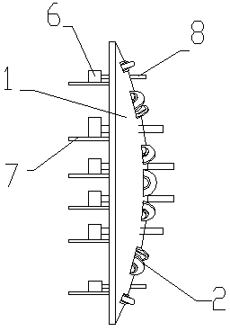
[0020] Embodiment 2: As shown in the figure, a drill-roll combination cutterhead structure for TBM, the cutterhead body 1 is arranged at the front end of the TBM, and its working surface is a spherical structure protruding outwards, and at the apex of the working surface The center hob group 5 is set at the position, and the center hob group 5 is formed by connecting four disc-shaped hobs 2 to each other through the cutter shaft in sequence. On the working surface of the cutter head body 1, the center of the cutter head body 1 is the center of the circle, and a plurality of disc-shaped hobs 2 are evenly arranged on the circles with different radii, and the disc-shaped hobs 2 on the circles with the same radius form a hob group, and earth and stone discharge holes 3 are evenly arranged between adjacent hob groups. In each hob unit, a drill operation hole 4 is set between two adjacent disc-shaped hobs 2, and the back side of the cutter head body 1, that is, the side opposite to t...


PUM


Abstract

Disclosed is a drilling and rolling combination cutter disc structure for a TBM (tunnel boring machine). The drilling and rolling combination cutter disc structure for the TBM is characterized in that a working face of the drilling and rolling combination cutter disc structure is a spherical face which is protruded outwards, a plurality of hob sets different in radius are arranged on the working face and around the center of a cutter disc body, each hob set comprises a plurality of disc type hobs, drilling machine operation holes are formed between each two adjacent disc type hobs, a rail and a rock drilling machine which slides along the rail are arranged on one side of the cutter disc body and along the direction opposite to the TBM work direction, drill bits of the rock drilling machine can stretch out or retract through the drilling machine operation holes, soil and stone discharge holes are located between each two adjacent hob sets and used to discharge excavated soil and stone from the soil and stone discharge holes, and the other rock drilling machine is arranged at the center of the cutter disc body in the same mode. According to the drilling and rolling combination cutter disc structure for the TBM, the rock drilling machines are added on the cutter disc body, and therefore a combination of the drilling machines and the hobs is achieved, rock breaking efficiency is improved, torque of the cutter disc body and the disc type hobs is reduced, and the excavation area of a cutter disc is increased by improving the structure of the cutter disc body and optimizing the arrangement mode of the hobs.

Description

technical field [0001] The invention belongs to the technical field of rock breaking, and mainly relates to a drill-roll combined cutter head structure used for TBM. Background technique [0002] TBM is a full-face hard rock tunneling machine, which can realize the processes of tunneling, support, slag discharge and other processes and operate continuously. It has the advantages of fast tunneling speed, environmental protection, and high comprehensive benefits. It can realize deep burial in complex geographical features that are difficult to achieve by traditional drilling and blasting methods. In the construction of long tunnels, under the action of thrust, the disc-shaped hob installed on the cutter head presses against the rock surface. With the rotation of the cutter head, the disc-shaped hob revolves around the central axis of the cutter head and rotates around its own axis at the same time. Under the strong thrust and torque of the cutter head, the hob rolls on the fix...

Claims


Application Information

Patent Timeline
Patent Type & Authority Applications(China)
IPC IPC(8): E21D9/10
Inventor 常家东王海霞
Owner LUOYANG INST OF SCI & TECH
Why Eureka
Try Eureka