Efficient vacuum water bath dust collector

A dust collector and vacuum technology, applied in chemical instruments and methods, dispersed particle separation, use of liquid separators, etc., can solve problems such as affecting the stability of emission indicators, incapable of dust-laden flue gas dust removal, and increasing operating costs, and achieve higher The effect of dust removal efficiency, convenient operation and maintenance, and reduction of operating costs

Active Publication Date: 2016-05-11
YONGAN HONGSHENG IND & TRADE CO LTD
View PDF6 Cites 0 Cited by
  • Summary
  • Abstract
  • Description
  • Claims
  • Application Information

AI Technical Summary

Problems solved by technology

This water-bath dust collector has the characteristics of high dust removal rate, energy saving, and low noise, but it has the following problems: (1) Since the guide bucket, rotary bucket, and spiral impeller are installed in the housing, it is very difficult to Maintenance; (2) Since the dust removal water medium is stored in the bathroom, with the prolongation of the bath time, the water quality is getting worse and worse, and the dust removal effect is getting worse and worse, which affects the stability of the emission index; (3) When the dust removal When the indoor dust is deposited to a certain extent, it is necessary to manually open the sewage valve to discharge it to the settling tank, which is inconvenient to operate and increases the operating cost; (4) When the dust is discharged, the dust removal water medium is also discharged at the same time , therefore, during this period of time, the dust-laden flue gas cannot be dedusted

Method used


Image

  • Efficient vacuum water bath dust collector
  • Efficient vacuum water bath dust collector
  • Efficient vacuum water bath dust collector

Examples


Embodiment Construction

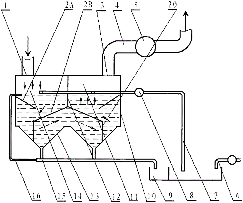
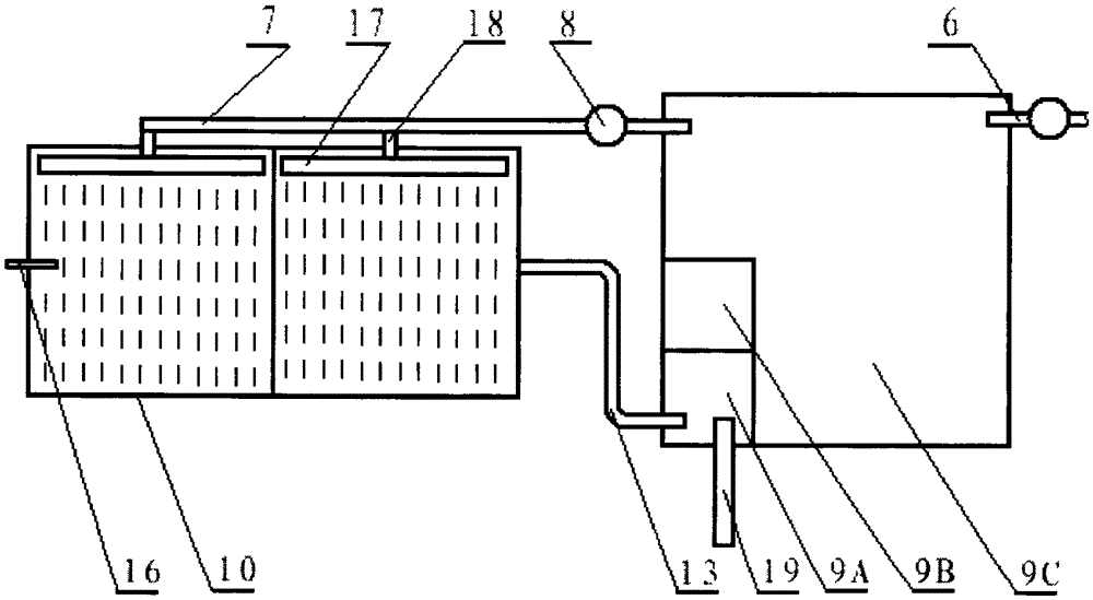
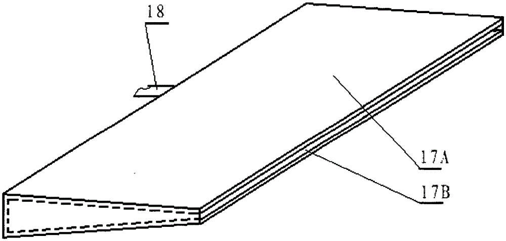
[0013] The structure of an embodiment of the present invention, such as figure 1 , figure 2 , image 3 , Figure 4 As shown, a high-efficiency vacuum water bath dust collector includes a smoke inlet 1, a smoke guide plate 2, a smoke outlet 3, a smoke exhaust pipe 4, an exhaust fan 5, an automatic limit water supply mechanism 6, a water inlet pipe 7, and a water pump 8. Settling tank 9, shell 10, smoke outlet chamber 11, partition 12, dust exhaust chamber 13, smoke inlet chamber 14, dust exhaust pipe 15, overflow pipe 16, nozzle 17, water outlet 18 of water inlet pipe 7, Timing slag cleaning machine 19, flue gas splitter plate 20, the water inlet of overflow pipe 16 is located in the housing 10, the water outlet is connected with the dust discharge pipe 15, and the dust discharge chamber 13 is in the shape of a large upper cone and a lower cone, located in the Below the housing 10, one end of the dust discharge pipe 15 is connected to the lower end of the dust discharge cha...


PUM


Abstract

The invention provides a high efficient vacuum water-bath deduster. The deduster comprises a shell, a sedimentation basin, a dust exhaust pipe, a dust exhaust chamber, and a water inlet pipe; the dust exhaust chamber is arranged under the shell, one end of the dust exhaust pipe is connected to the lower end of the dust exhaust chamber, the other end of the dust exhaust pipe is arranged in the sedimentation basin, and the center of the water inlet pipe is provided with a water pump. The deduster is characterized by also comprising a smoke evacuating pipe, a drawing fan, a partition plate, an automatic limiting and water-supplementing mechanism, and a regular slag cleaning machine; the drawing fan is arranged in the center of the smoke evacuating pipe, the partition plate is fixedly arranged in the upper part of the shell center so as to divide the upper part of the shell into a smoke-in chamber and a smoke-out chamber, the automatic limiting and water-supplementing mechanism is arranged on a proper position of the final stage of the sedimentation basin, and the regular slag cleaning machine is arranged on a proper position of the first stage of the sedimentation basin. The dust-containing flue gas is driven by the drawing fan to go through and be washed by the flowing dedusting water medium, and thus the stability of discharge indexes is achieved. The dusts in the sedimentation basin can be regularly removed by the regular slag cleaning machine, and the dedusting water medium can be supplemented by the automatic limiting and water-supplementing mechanism, so the automation degree of the deduster is high.

Description

technical field [0001] The invention relates to a high-efficiency vacuum water bath dust collector. Background technique [0002] At present, the wet dust collectors that use water as the dust removal medium can be roughly divided into spray dust collectors, water film dust collectors and composite dust collectors that combine water film spray. These types of dust collectors are used in practice. In the process of use, there are problems such as incomplete dust removal and excessive exhaust emissions. The reason is that the dusty flue gas cannot fully contact with water. In order to solve the above problems, Chinese patent CN100386133C discloses a water-bath dust collector, which includes a shell, a guide barrel and a rotating barrel installed on it, one end of the smoke guide barrel is inserted into the shell, and the other end is provided with a spiral side inlet. There is a main shaft extension hole at the center of the top of the smoke guide barrel, and the main shaft p...

Claims


Application Information

Patent Timeline
Patent Type & Authority Patents(China)
IPC IPC(8): B01D47/02
Inventor 张自明
Owner YONGAN HONGSHENG IND & TRADE CO LTD
Why Eureka
Try Eureka