One-axle multi-cylinder multi-dimensional ball hammer type micro-nano high-energy ball mill

A high-energy ball mill, multi-dimensional technology, applied in grain processing and other directions, can solve the problems of many blind spots that are not accessible to the grinding balls, affecting the ball milling efficiency and powder particle size uniformity, and short motion trajectories. Efficiency and output, stable operation effect

Inactive Publication Date: 2014-10-29
深圳市来源新材料科技有限公司
6 Cites 17 Cited by

AI-Extracted Technical Summary

Problems solved by technology

[0002] Most of the existing ball mills are rotary, vibrating or eccentric rotary ball mills. The eccentric rotary ball mills that are widely used at present often use the motor to rotate the main shaft, so that the eccentric wheel on the main shaft rotates accordingly, so that the ball mill cylinder can be rotated between the eccentric wheel and the eccentric wheel. Under the action of the spring...

Abstract

The invention discloses a one-axle multi-cylinder multi-dimensional ball hammer type micro-nano high-energy ball mill. The ball mill is characterized in that a round disk is driven through the rotation of an eccentric shaft driving system and an eccentric shaft support system, a plurality of cylindrical milling tanks are arranged on the round disk, the tank body is driven to regularly swing in a multi-dimension manner up and down, left and right, front and back through the synchronous rotation of the eccentric shaft and the eccentric shaft support system, the ball material in the tank body is thrown up to produce multi-dimensional hammer action, so that fierce impacting, chopping and grinding in multi-dimension can be achieved. Since the multi-dimensional impacting and grinding have no dead angle, the material can be ground into uniform micro-nano powder, the processing efficiency, the yield and the quality of the micro-nano powder are obviously improved; the ball mill has a stable structure, can be easily enlarged to form the scale production, and is suitable for the demand of nanometer application engineering.

Application Domain

Technology Topic

Image

  • One-axle multi-cylinder multi-dimensional ball hammer type micro-nano high-energy ball mill
  • One-axle multi-cylinder multi-dimensional ball hammer type micro-nano high-energy ball mill
  • One-axle multi-cylinder multi-dimensional ball hammer type micro-nano high-energy ball mill

Examples

  • Experimental program(1)

Example Embodiment

[0026] Example:
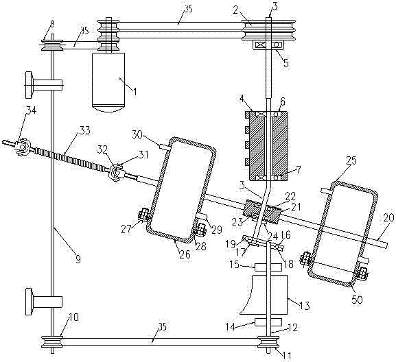
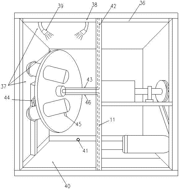
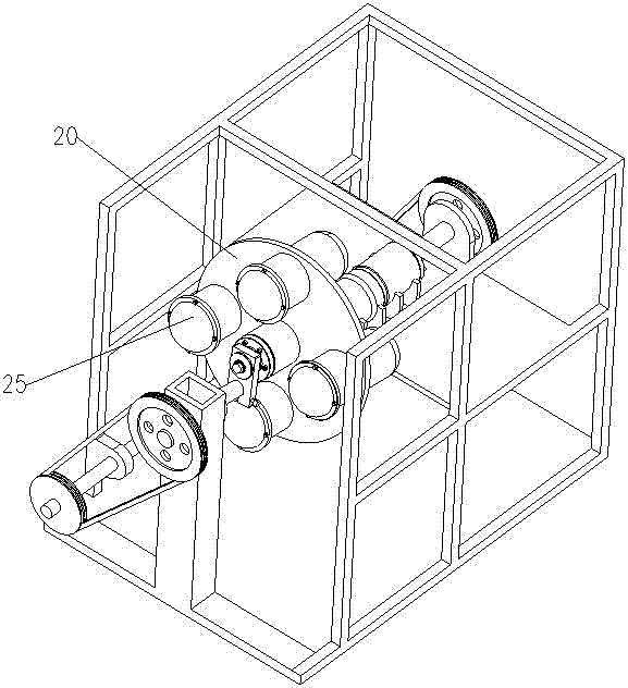
[0027] As shown in the figure, the technical solution provided by the present invention is a one-axis multi-cylinder multi-dimensional ball hammer type micro-nano high-energy ball mill, a frame 36 and an eccentric shaft drive device, an eccentric shaft support device and a rotary disc crushing device installed in the frame, so The eccentric shaft drive device is composed of a frequency converter control motor 1, a pulley 2, an eccentric shaft 3, a bearing seat 4, 5 and a number of bearings 6, 7. One end of the eccentric shaft 3 is installed on the pulley 2, and the other end is connected to the pulley 2. The bearings 6 and 7 installed on the bearing seat are fixedly connected. The pulley 2 is connected to the inverter control motor 1 through the transmission belt 35, and then drives the eccentric shaft 3 to move. The angle of the eccentric shaft 3 is 10-20 degrees. On the contrary, the smaller the machine is, the larger the angle is, that is, when the machine is larger, the distance between the edge of the disc 20 and the axis of the eccentric shaft 3 will be larger, and the relative eccentricity angle will be smaller. The closer the distance between the edge and the eccentricity, the smaller the movement of the cylindrical grinding jar, and the larger the angle of the eccentric shaft 3.
[0028] The eccentric shaft support device includes one or more pulleys 8, 10, 11, a linkage shaft 9, a support shaft 12, a support seat 13, and bearing seats 14, 15. The bearing seats 14, 15 are installed on the two sides of the support seat 13. At the end, the support base 13 is fixed on the support shaft 12, one end of the support shaft 12 is installed with the pulley 11, and the other end is connected with an oblique connecting plate 16, which is fixed by the eccentric shaft top cover 17 and connected with the eccentric shaft 3, The inclined connecting plate is fixed by screws 18 and 19. Both ends of the linkage shaft 9 are equipped with pulleys 8 and 10. The pulley 8 at one end of the linkage shaft is connected with the above-mentioned frequency converter control motor 1 through the transmission belt 35. The drive belt 35 is connected with the pulley 11 installed on the above-mentioned support shaft 12. The eccentric shaft support system is also the same frequency converter to control the motor 1. The belt pulley 8 at the front end of the linkage shaft 9 is driven by the conveyor belt 35 and drives the pulley 10 at the rear end of the linkage shaft. Then the pulley 11 in the front section of the support shaft is driven, the support shaft 12 is movably matched with the bearing seats 14 and 15, and the other end of the support shaft 12 is fixed with the inclined connecting plate 16 and the inclined connecting plate at the same time with the eccentric shaft 3, so as to achieve synchronous rotation with the eccentric shaft. The eccentric shaft 3 is supported. Since the supporting shaft 12 can bear 40% of the torsion force of the eccentric shaft, the wearing parts are turned to the slanted connecting plate 16 or the bearings 14 and 15 on the support base 13, so that the eccentric shaft 3 is protected and the equipment runs relatively Stable and long life cycle.
[0029]The turntable crushing device includes a disc 20 , a turntable bearing seat 21 and more than one cylindrical grinding pot 25 , the turntable bearing seat 21 is fixed at the center of the disc 20 , and the turntable bearing seat 21 is fixed with the above-mentioned eccentric shaft 3 . The cylindrical grinding pots 25 are evenly distributed and installed on the disc 20. The number of cylindrical grinding pots can be several or dozens or even dozens. The outer end of the disc 20 is also installed with a first joint bearing 31. , the lower end of the first joint bearing 31 is provided with a tension spring 33 and a universal joint 32, a second joint bearing 34 is arranged between the tension spring 33 and the frame 1, and one end of the tension spring 33 passes through the universal joint 32 It is connected with the first joint bearing 31, and the other end is connected with the second joint bearing 34; the second joint bearing 34 is fixed on the frame, and the disk 20 adopts a vertical disk or a horizontal disk, and the present invention adopts a vertical disk A disc, on which there are several, dozens or dozens of horizontal cylindrical grinding jars arranged radioactively. One rotation of the eccentric shaft can make the cylindrical grinding jar move in multiple different directions. The cylindrical grinding jar swings up and down, left and right, and back and forth once, and the balls impact once at a high speed, which can be regarded as "rotation". The crushed items are plants, minerals, and non-metals. The object is metal and the eccentric shaft rotates 600-800 times per minute, and the "revolution" of the disc 20 is controlled by a soft pulling combination. The soft pulling combination is a tension spring 33 connected by the first joint bearing 31 on the edge of the disc and the universal joint 32, and the other end of the tension spring 33 is also connected with a second joint bearing 34 and the universal joint and fixed on the machine. On the shelf, no matter how the disc swings, the tension spring can pull the disc, so that it cannot "revolve", because once the "revolution" runs, it will offset the rotation of the roulette and the grinding pot, making the multi-dimensional swing and the ball hammer. Action disappears.
[0030] The present invention is further described below:
[0031] like figure 1 As shown, the angle of the eccentric shaft 3 designed by the present invention is 10-20 degrees, which is rotated with the help of the eccentric shaft driving device and the eccentric shaft supporting device, and drives a vertical disc to rotate, and the disc is equipped with a plurality of horizontal The cylindrical grinding jar, the eccentric shaft 3 and the supporting system are rotated to drive the cylindrical grinding jar to swing up and down, left and right, and front and back regularly to form multiple movements of high-energy ball milling.
[0032] Among them, the vertical roulette crushing system:
[0033] The roulette crushing system is composed of a fixed bearing seat 21 in the center of a disc 20, front and rear push bearings 22, 23 and are tightly mounted on the eccentric shaft 3 with nuts 24, and several vertical or horizontal disc radioactive devices. Dozens or dozens of horizontal cylindrical grinding pots 25 .
[0034] The inner wall of the cylindrical grinding pot 25 is designed with no dead ends, and the internal transition sections are all arc-shaped 50. The cylindrical grinding pot 25 can be provided with a grinding pot cover 26 on the tank body and can be sealed with screws 27 and "O" type. The rubber ring 28 seals it with the tank body, and the upper and lower walls of the tank body are provided with a feeding port 29 and a feeding port 30.
[0035] recombination Figure 3 to Figure 10 To further explain the roulette crushing system:
[0036] Due to the limitation of the tension spring 33, the disc cannot revolve, but under the toggle of the eccentric shaft 3, the eccentric shaft 3 can rotate once at 10-20 degrees to complete the following actions: up and down, left and right, and can It tilts forward and backward, twists and swings left and right, thereby driving the multi-dimensional ball hammer of the grinding medium to impact the material.
[0037] The movement trajectory of the disc and the cylindrical grinding jar is further explained in detail. The specific point is to decompose the eccentric shaft 3 into 4 movements by rotating one circle. be explained.
[0038] first step: Figure 5 , Figure 8 As shown, when the eccentric shaft deviates to the left, the disc swings to the left, and the left cylindrical grinding pot swings back, while the rear part of the upper and lower cylindrical grinding pots swings back, and the right cylindrical grinding pot swings back. The mill jar swings forward.
[0039] Step 2: Image 6 , Figure 10 As shown, when the eccentric shaft is deflected to the lower side, the upper part of the disc swings forward and the upper cylindrical grinding pot swings forward, while the lower part of the disc swings backward and sinks at the same time, so that the lower cylindrical grinding pot is also backward Swing, the cylindrical grinding pots on the left and right sides are tilted upward.
[0040] The third step: as image 3 , Figure 7 As shown, when the eccentric shaft turns to the right, the disc swings to the right and the right cylindrical grinding jar swings to the right, while the right cylindrical grinding jar swings backward, and the left disc moves forward The swing drives the cylindrical grinding tank to swing forward and the rear of the upper and lower cylindrical grinding tanks swings to the right.
[0041] the fourth step: Figure 4 , Figure 9 As shown, when the eccentric shaft turns to the upper side, the disc tilts upward, the upper tank body swings backward, and the lower part of the disc tilts forward, which drives the lower cylindrical grinding tank to swing forward, while the left and right cylinders swing forward. The front of the grinding jar rises and the rear swings down.
[0042] recombination figure 2 To further explain the water cooling system of the crushing chamber:
[0043] The first method is that the water cooling device adopts a four-wall sealing structure 37 for the rotary disc pulverizing device placed in the frame. A number of water shower heads 39 for spraying the cylindrical grinding tank are sequentially installed on the top, and a water tank 40 is arranged at the bottom end of the water tank, and a drain port 41 is installed on the water tank.
[0044] The second method is to use the water cooling device to set up a water pipeline circulation system on the outer end surface of the cylindrical grinding tank. The water pipeline circulation system includes a water inlet pipe 42, an elastic hose 43, and a water inlet on the cylindrical grinding tank. 44. The lower water outlet 45 of the cylindrical mill tank, the elastic water outlet hose 46 and the down water pipe 47, the water inlet pipe 42 is installed on the frame 36, and is connected with the elastic hose 43, and the elastic hose 43 is connected to the cylindrical mill. The upper water inlet 44 of the tank is connected by pipeline, the upper water inlet 44 of the cylindrical grinding tank is connected to the lower water outlet 45 of the cylindrical grinding tank, and the lower water outlet 45 of the cylindrical grinding tank is connected to the water pipe 47 through the elastic water outlet hose 46. Connection, the downpipe 47 is installed on the frame 46, and is connected with the elastic water outlet hose, and the water outlet enters the cold circulating water tank through the downpipe 47. The successful control of the temperature is related to the thickness of the water pipe, the pressure of the water pump and the adjustment of the chiller.
[0045] The choice of two cooling methods is: spray water cooling should be used for small experimental machines, and water circulation cooling method for grinding tank interlayer should be used for production models.
[0046] Since the jar on the vertical disc in the present invention is horizontal, if it is an experimental machine, the horizontal jar can be disassembled, and the grinding jar can be placed on a laboratory bench or in a vacuum glove box to open for operation. However, on the production tank of the large model, the horizontally placed tank is welded on the disc 20. The tank cover 26 is sealed and connected to the tank through the sealing rubber ring 28 and the screw 27. Only when the tank is cleaned Only when the inner wall is opened. During the production feeding, the ball and dry material or ball and slurry are added from the feeding port 30 to the tank through the elastic plastic tube. , screw it to the bottom. When unloading, first fix the elastic plastic tube at the discharge port and then turn the sealing bolt. At this time, start the slow rotation drive for 25 rpm, and then all the balls can be discharged.

PUM

no PUM

Description & Claims & Application Information

We can also present the details of the Description, Claims and Application information to help users get a comprehensive understanding of the technical details of the patent, such as background art, summary of invention, brief description of drawings, description of embodiments, and other original content. On the other hand, users can also determine the specific scope of protection of the technology through the list of claims; as well as understand the changes in the life cycle of the technology with the presentation of the patent timeline. Login to view more.

Similar technology patents

Extrusion molding device and extruder

PendingCN114148024AIncrease widthImprove production and efficiencyFood shapingShaping pressMoulding deviceEngineering
Owner:沁海(北京)食品有限公司

Reciprocating type continuous roller receiving device capable of being used for electrostatic spinning

InactiveCN105803542AImprove poor uniformityImprove production and efficiencyFilament/thread formingEngineeringNanofibrous membrane
Owner:上海科涤环保科技有限公司

Small stirrup making device of hoop bending machine

PendingCN111589979AImprove production and efficiencyCompact structureIndustrial engineeringStirrup
Owner:綦延青

Plant protoplast culturing method

PendingCN109988740AImprove production and efficiencyOvercoming yield bottomPlant cellsProtoplasmSuspension culture
Owner:HEFEI NORMAL UNIV

Classification and recommendation of technical efficacy words

  • Improve production and efficiency
  • Run smoothly

Fusion protein containing RNA binding protein and expression vector matched with fusion protein

ActiveCN111718419AImprove production and efficiencyReduce restrictionsFusion with RNA-binding domainFungiCell freeExpression vector
Owner:KANGMA SHANGHAI BIOTECH LTD

Method for producing dress one-piece flow

InactiveCN101711606AImprove production and efficiencyShort production cycleClothes making applicancesEngineeringShift systems
Owner:ZHONGSHAN DEMEI SPORTS PROD

Combined functional rod-toothed crusher

InactiveCN101804372AReduce crushing powerImprove production and efficiencyGrain treatmentsElectrical controlElectric machinery
Owner:SHENYANG HENGXING MACHINERY

Method and apparatus for false twiting and drawing animal fibre

InactiveCN1401839AImprove fiber qualityImprove production and efficiencyDrafting machinesPre treatmentWetting
Owner:TIANJIN POLYTECHNIC UNIV +1
Why Eureka
Try Eureka