An optical system for 3D printing and a control method thereof

A 3D printing and optical system technology, applied in the field of 3D printing, can solve the problems of slow speed and low efficiency

Inactive Publication Date: 2014-10-29
GUANGZHOU INST OF ADVANCED TECH CHINESE ACAD OF SCI
View PDF7 Cites 6 Cited by
  • Summary
  • Abstract
  • Description
  • Claims
  • Application Information

AI Technical Summary

Problems solved by technology

This printing method is slow and inefficient, which is a major bottleneck in the development of 3D printing technology.

Method used


Image

  • An optical system for 3D printing and a control method thereof
  • An optical system for 3D printing and a control method thereof
  • An optical system for 3D printing and a control method thereof

Examples


Embodiment 1

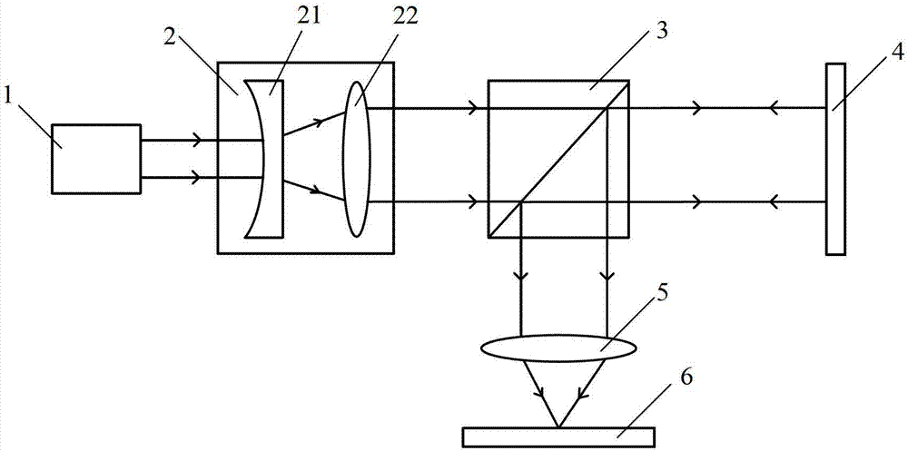
[0076] refer to figure 1 , an optical system for 3D printing, including a laser 1, a beam expander system 2, a beam splitter 3, a spatial light modulator 4 and a focusing system 5, the spatial light modulator 4 is connected to a computer for generating a target modulation pattern, The spatial light modulator 4 is used to generate the modulation pattern after receiving the target modulation pattern generated by the computer and modulate the beam irradiated to the spatial light modulator 4. The beam emitted by the laser 1 is expanded into a parallel beam with a large diameter by the beam expander system 2 and irradiate the beam splitter 3, wherein a part of the expanded beam passes through the beam splitter 3 and reaches the spatial light modulator 4 for modulation, and after the modulated beam is reflected back to the beam splitter 3, a part of the modulated beam passes through the focusing The system 5 is focused and irradiated onto the 3D printed target plane 6 .

[0077] In...

Embodiment 2

[0081] refer to figure 1 , an optical system for 3D printing, including a laser 1, a beam expander system 2, a beam splitter 3, a spatial light modulator 4 and a focusing system 5, the spatial light modulator 4 is connected to a computer for generating a target modulation pattern, The spatial light modulator 4 is used to generate the modulation pattern after receiving the target modulation pattern generated by the computer and modulate the beam irradiated to the spatial light modulator 4. The beam emitted by the laser 1 is expanded into a parallel beam with a large diameter by the beam expander system 2 and irradiate the beam splitter 3, wherein a part of the expanded beam passes through the beam splitter 3 and reaches the spatial light modulator 4 for modulation, and after the modulated beam is reflected back to the beam splitter 3, a part of the modulated beam passes through the focusing The system 5 is focused and irradiated onto the 3D printed target plane 6 .

[0082] In...

Embodiment 3

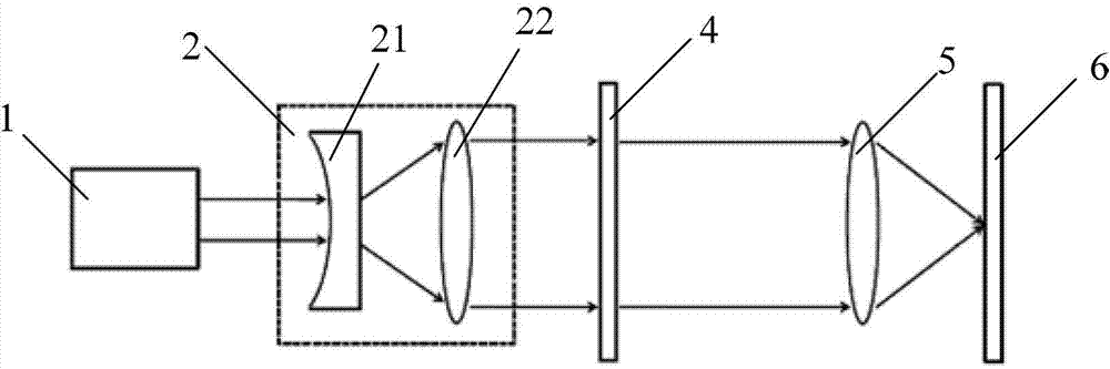
[0086] refer to figure 2 , an optical system for 3D printing, including a laser 1, a beam expander system 2, a spatial light modulator 4 and a focusing system 5, the spatial light modulator 4 is connected to a computer for generating a target modulation pattern, the spatial light modulator 4 It is used to generate the modulation pattern after receiving the target modulation pattern generated by the computer and modulate the beam irradiated to the spatial light modulator 4. The beam emitted by the laser 1 is expanded into a large-diameter parallel beam by the beam expander system 2 and irradiated to the spatial light modulator 4. The modulator 4 performs modulation, and the modulated light beam is focused by the focusing system 5 and irradiated onto the 3D printed target plane 6 .

[0087] In this embodiment, the beam expander system 2 includes a negative lens 21 and a positive lens 22, the axis of the negative lens 21 and the axis of the positive lens 22 are collinear, and th...


PUM


Abstract

An optical system for 3D printing and a control method thereof are disclosed. The optical system comprises a laser, a beam expanding system, a beam splitter, a spatial light modulator and a focusing system. The spatial light modulator is connected to a computer used for generating a target modulation pattern. The spatial light modulator receives the target modulation pattern generated by the computer and then generates the modulation pattern. A light beam emitted by the laser is subjected to beam expansion into a parallel beam by the beam expanding system and the parallel beam irradiates the beam splitter. The light beam after partial beam expansion reaches the spatial light modulator to be modulated after passing through the beam splitter. After the modulated light beam is reflected to the beam splitter, the light beam after partial beam expansion irradiates a target plane of 3D printing after being focused by the focusing system. According to the optical system and the control method, optical modulation and focusing demodulation are performed by adopting the modulation pattern as a unit, and printing line by line, printing paragraph by paragraph and even printing of the whole plane can be achieved, thus increasing the printing efficiency, accelerating the printing speed, and guaranteeing the 3D printing quality. The optical system and the control method can be widely used in the field of 3D printing.

Description

technical field [0001] The invention relates to the field of 3D printing, in particular to an optical system for 3D printing and a control method thereof. Background technique [0002] 3D printing technology has the ability to directly realize the digital model, which can change the traditional design and manufacturing methods. 3D printing is currently used in aerospace, medical, automotive, and many other fields. However, the application of 3D printing technology in industry still faces many problems, one of the key problems is the slow printing speed. Existing 3D printing equipment, including laser selective sintering (SLS), laser selective melting (SLM), etc., all rely on single-beam or multi-beam laser point-by-point printing, mirrors and lenses controlled by micro-electromechanical systems Combination, to manipulate the movement of the beam focus, so as to achieve point-by-point printing. This printing method is slow and inefficient, which is a major bottleneck in th...

Claims


Application Information

Patent Timeline
Patent Type & Authority Applications(China)
IPC IPC(8): B29C67/00
CPCB29C67/00B33Y30/00B29C64/153B29C64/393Y02P10/25B22F10/28B22F10/80B22F12/44B33Y10/00B33Y50/02B23K26/342B23K26/0648B23K26/067B29K2105/251
Inventor 郑渚艾澈熙任云鹏杜如虚
Owner GUANGZHOU INST OF ADVANCED TECH CHINESE ACAD OF SCI
Why Eureka
Try Eureka