A Winding Mechanism Favorable to Reduce Winding Cost

A winding mechanism and a cost-effective technology are applied in the field of cable storage and protection devices, which can solve the problems of reduced winding quality and unfavorable winding efficiency, and achieve the effects of good winding quality, favorable winding quality and light weight.

Active Publication Date: 2017-01-25
SICHUAN TIANWEI ELECTRONICS
View PDF6 Cites 0 Cited by
  • Summary
  • Abstract
  • Description
  • Claims
  • Application Information

AI Technical Summary

Problems solved by technology

[0003] In view of the above-mentioned prior art, the uniform distribution of the cables on the axis of the spool and the tensile stress on the cables before being wound to the spool require manual control or auxiliary auxiliary mechanisms, which is not conducive to winding Efficiency, winding quality and reducing the quality and volume of winding rollers, the present invention provides a winding mechanism that is beneficial to reduce winding costs

Method used


Image

  • A Winding Mechanism Favorable to Reduce Winding Cost
  • A Winding Mechanism Favorable to Reduce Winding Cost
  • A Winding Mechanism Favorable to Reduce Winding Cost

Examples


Embodiment 1

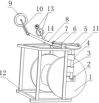
[0027] Such as figure 1 and figure 2, a winding mechanism that is conducive to reducing the cost of winding, including a frame 12 and a wire wheel 1 fixed on the frame 12, and the wire wheel 1 is also connected with a drive for driving the wire wheel 1 to rotate around its axis Motor, the frame 12 is also provided with an adjustment device and a cable tensioning device for realizing the uniform distribution of cables on the wire pulley 1;

[0028] The adjustment device includes a slide bar 6, a sliding sleeve 7 sleeved on the slide bar 6, a lead wheel frame 10, a lead wheel 9, a bolt seat 8, a reversing shaft 3, a bevel gear pair 2 and a drive rod 5. The axis of the slide bar 6 is parallel to the axis of the wire wheel 1, one end of the bolt seat 8 is fixedly connected with the sliding sleeve 7, the other end of the bolt seat 8 is bolted to the lead wheel frame 10, and the lead wheel frame 10 is opposite to the bolt seat 8 The included angle is adjustable, the lead wheel 9 ...

Embodiment 2

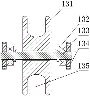
[0033] The present embodiment is further limited on the basis of embodiment 1, as figure 1 and figure 2 , in order to make the reversing shaft 3 move through the compact brake sleeve 7 of the driving rod 5 during the rotation, the reversing shaft 3 is also fixed with a drive disc 11 perpendicular to the reversing shaft 3, the driving A column is fixed on the disk 11 and the sliding sleeve 7, and a bearing is arranged on the column, and the inner rings of the two bearings are respectively fixedly connected with the corresponding columns, and the two ends of the driving rod 5 are respectively connected with the outer rings of the two bearings. Fixedly connected, and the two columns are parallel to the reversing shaft 3. Using the drive plate 11 to realize the excessive connection between the reversing shaft 3 and the drive rod 5 facilitates the realization that the center of gravity of the reversing shaft 3 deviates less from the axis of the reversing shaft 3, which is benefic...

Embodiment 3

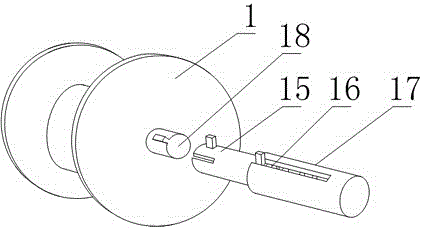
[0035] The present embodiment is further limited on the basis of embodiment 1, as figure 1 and figure 2 , in order to reduce the compressive stress of the sliding sleeve 7 and the sliding rod 6 when the driving rod 5 drives the sliding sleeve 7 to move along the sliding rod 6, the driving rod 5 and the sliding rod 6 are located in the same plane.


PUM


Abstract

The invention discloses a winding mechanism for facilitating reduction of the winding cost. The winding mechanism comprises a machine frame and a reel, wherein a driving motor is further connected onto the reel, and an adjusting device and a cable tensioning device are further arranged on the machine frame. The adjusting device comprises a sliding rod, a sliding sleeve, a lead wire wheel carrier, a lead wire wheel, a threaded seat, a reversing shaft, a bevel gear pair and a driving rod. A bearing seat is further arranged on the machine frame. The cable tensioning device comprises a pressing wheel carrier and two pressing wheels, wherein a gap for a cable to pass through is reserved between the sides of two pressing wheels. The reel comprises a reel body and a reel shaft, wherein at least one end of the reel shaft is connected with a reel dismounting portion, and the reel dismounting portion comprises a spring, a first sleeve and a second sleeve. The winding mechanism is simple in structure and convenient to manufacture and carry. Coils can be wound tightly, the storage quantity of the reel is increased, and the winding mechanism is suitable for storage of cables within a certain wire diameter range, further has high winding speed, meanwhile is wide in using range and facilitates reduction of the cable winding cost.

Description

technical field [0001] The invention relates to a cable storage and protection device, in particular to a winding mechanism which is beneficial to reduce winding costs. Background technique [0002] In the prior art, power cables and communication cables are used in various fields. In the production and packaging of cables, laying and storage of cables at zero time, winding rollers are required. The main winding part of the winding rollers is the wire wheel. , through the rotation of the wire wheel, the cable is wound on it in a circle shape, so as to reduce the space occupied by the above-mentioned cable, prevent the local excessive bending and deformation of the cable, and facilitate the life, storage and transportation of the cable. Evenly winding the cable on the reel and tightening the hoop layer by layer is the most effective way to maximize the use of the reel. In the prior art, the uniform distribution of the cable on the reel axis and the cable before being wound to...

Claims


Application Information

Patent Timeline
Patent Type & Authority Patents(China)
IPC IPC(8): B65H54/30B65H54/40B65H59/10
Inventor 奂建东陈建杨德志杨海燕
Owner SICHUAN TIANWEI ELECTRONICS
Why Eureka
Try Eureka