
Storage battery charging device

A charging device and battery technology, which is applied to battery circuit devices, circuit devices, current collectors, etc., can solve the problems of inability to control charging current, affect battery life, and poor operating conditions, and achieve high requirements, reliable charging, and high stability. The effect of sexual control

Active Publication Date: 2014-10-29
ZHUZHOU CSR TIMES ELECTRIC CO LTD
View PDF6 Cites 4 Cited by
  • Summary
  • Abstract
  • Description
  • Claims
  • Application Information

AI Technical Summary

Problems solved by technology

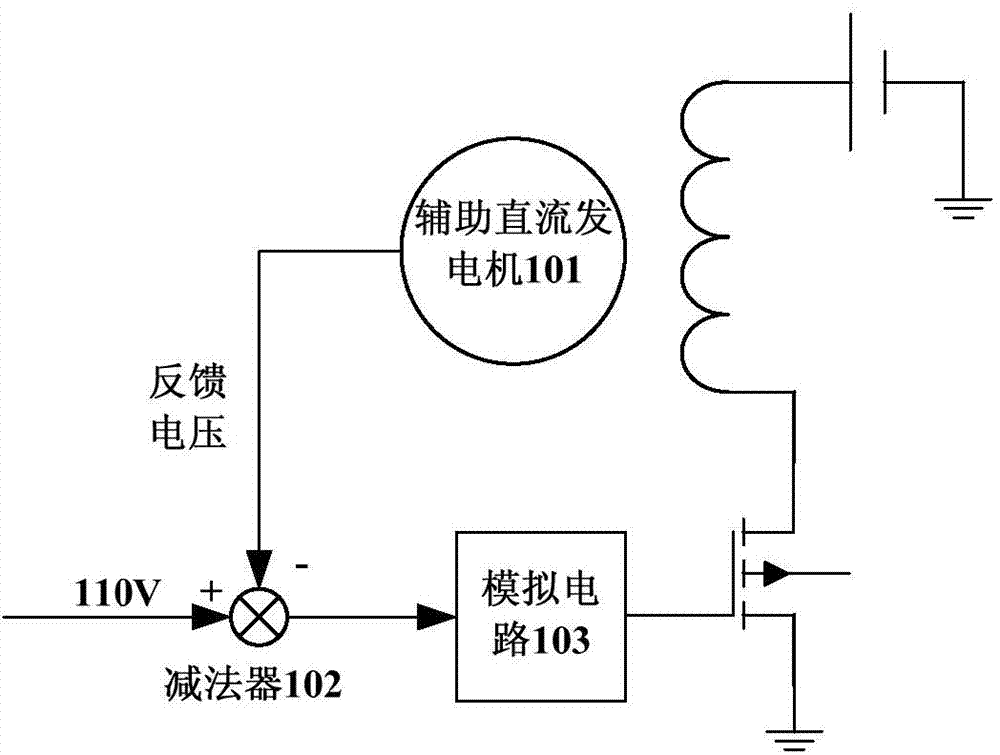
However, due to the complex working conditions of diesel locomotives, harsh operating conditions and other factors, there has never been a device that can meet the requirements of diesel locomotives and convert the AC power output from the auxiliary alternator into a stable DC power output to charge the battery. Therefore, there is a situation where the auxiliary AC generator on a locomotive supplies power to auxiliary equipment and the auxiliary DC generator charges the battery.
[0004] The voltage of the current auxiliary DC generator uses analog circuit devices such as operational amplifiers for constant voltage control, and the charging current cannot be controlled
And when the battery feed is serious, the constant voltage control will produce a charging current of hundreds of amperes, which will cause great damage to the battery and affect the life of the battery

Method used


Image

  • Storage battery charging device
  • Storage battery charging device
  • Storage battery charging device

Examples


Embodiment Construction

[0050] The implementation of the present invention will be described in detail below in conjunction with the accompanying drawings and examples, so as to fully understand and implement the process of how to apply technical means to solve technical problems and achieve technical effects in the present invention. It should be noted that, as long as there is no conflict, each embodiment and each feature in each embodiment of the present invention can be combined with each other, and the formed technical solutions are all within the protection scope of the present invention.

[0051] Also, in the following description, for purposes of explanation, numerous specific details are set forth in order to provide a thorough understanding of embodiments of the invention. It will be apparent, however, to one skilled in the art that the present invention may be practiced without the specific details or in the particular manner described.

[0052] In addition, the steps shown in the flow dia...


PUM


Abstract

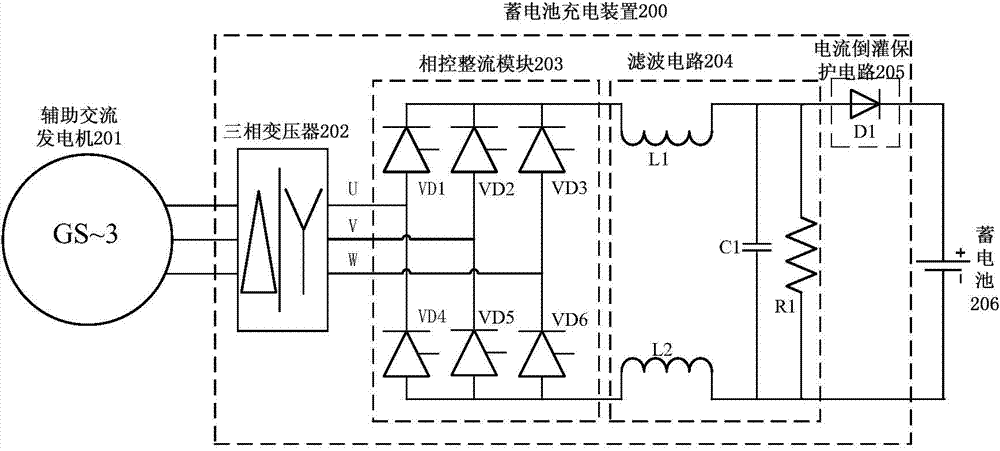
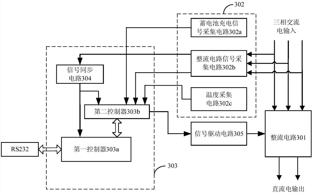
The invention discloses a storage battery charging device. The storage battery charging device comprises a phase-controlled rectification circuit, a filter circuit and an electric current reversing protective circuit, wherein the phase-controlled rectification circuit is connected with an external alternating current power supply and used for converting alternating current which is output by the external alternating current power supply to direct current, the phase-controlled rectification circuit adjusts output direct current according to obtained storage battery charging signals and a preset electric current curve, the filter circuit is connected with the phase-controlled rectification circuit and used for filtering the direct current, and the electric current reversing protective circuit is arranged between a storage battery and the filter circuit in a connecting mode and used for preventing electric current which is output by the storage battery from reversing to the filter circuit. By means of the storage battery charging device, the storage battery can be rapidly charged up, safety and reliability of the charging process can be guaranteed, meanwhile, control speed and control accuracy of a system can be greatly improved, high-accuracy high-stability control over strong electricity is achieved, and thereby, high requirements of a diesel locomotive for a control system under poor operating conditions can be met.

Description

technical field [0001] The invention relates to the technical field of power electronics, in particular to a storage battery charging device. Background technique [0002] At present, domestic diesel locomotives use auxiliary DC generators to charge the on-board batteries. The DC power output from the auxiliary DC generator will be regulated by the microcomputer auxiliary voltage regulation system and then sent to the battery, and the microcomputer auxiliary voltage regulation system can output 110V DC power in all speed ranges of the diesel engine to be used as a battery charging power supply, and to the Power supply for other auxiliary equipment on the locomotive. [0003] However, with the widespread use of AC generators with better performance and the need for energy saving, auxiliary AC generators are gradually replacing auxiliary DC generators, and various auxiliary equipment adapted to auxiliary AC generators have been widely used. However, due to the complex workin...

Claims


Application Information

Patent Timeline
Patent Type & Authority Applications(China)
IPC IPC(8): H02J7/04
Inventor 肖健刘松柏冯炳周少云班立权付果刘灿
Owner ZHUZHOU CSR TIMES ELECTRIC CO LTD
Learn More