Fluorescent sensor and sensor system

A fluorescence sensor, fluorescence technology, applied in the field of sensing systems, can solve the problem of difficult to obtain detection sensitivity and the like

Active Publication Date: 2014-10-29
TERUMO KK
View PDF10 Cites 2 Cited by
  • Summary
  • Abstract
  • Description
  • Claims
  • Application Information

AI Technical Summary

Problems solved by technology

[0008] However, the fluorescence sensor 130 can detect only the fluorescence emitted from the indicator 117 toward the direction of the photoelectric conversion element 112 , that is, downward.
Therefore, although the fluorescence sensor 130 is small, it is not easy to obtain high detection sensitivity.

Method used


Image

  • Fluorescent sensor and sensor system
  • Fluorescent sensor and sensor system
  • Fluorescent sensor and sensor system

Examples


no. 1 Embodiment approach >

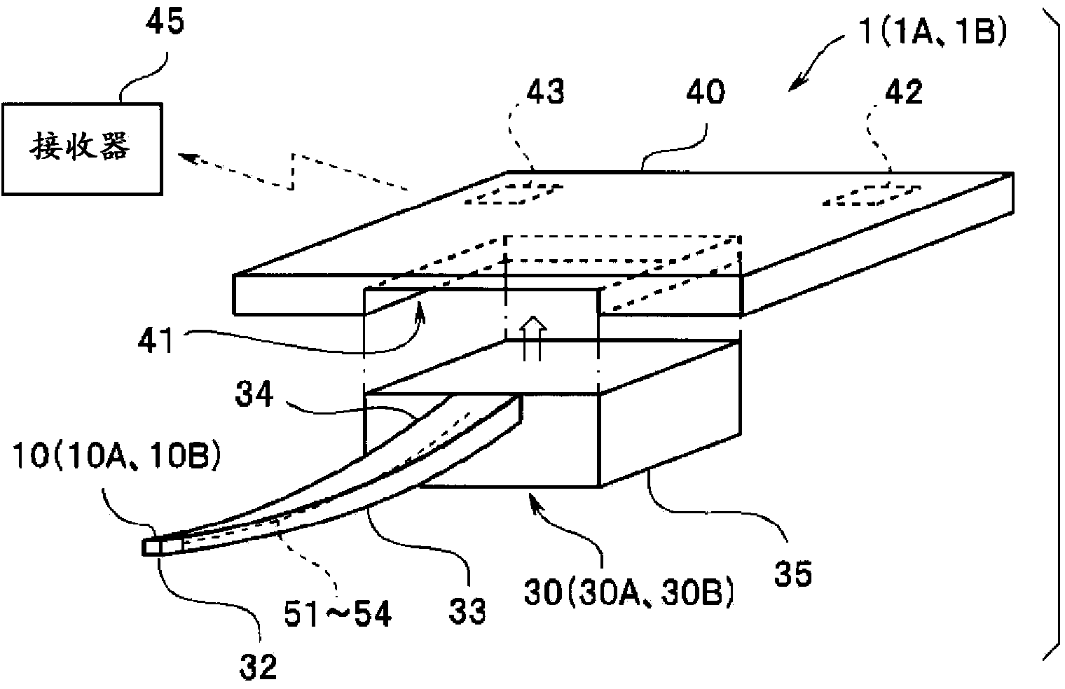
[0027] First, the fluorescence sensor 30 and the sensing system 1 according to the first embodiment of the present invention will be described. like image 3 As shown, the sensing system 1 has a fluorescent sensor 30 , a main body 40 and a receiver 45 that receives and stores signals from the main body 40 . Transmission and reception of signals between the main body 40 and the receiver 45 are performed wirelessly or by wire.

[0028] The fluorescence sensor 30 is composed of a needle portion 34 for puncturing a subject, and a connector portion 35 joined to the rear end portion of the needle portion 34 . The needle portion 34 has an elongated needle body portion 33 and a needle tip portion 32 including the sensing portion 10 as a main functional portion. The needle tip portion 32, the needle body portion 33, and the connector portion 35 may be integrally formed of the same material, or may be manufactured separately and joined together.

[0029] The connector portion 35 is d...

no. 2 Embodiment approach >

[0097] Next, the sensing system 1B and the fluorescence sensor 30B of the second embodiment will be described. Since the fluorescence sensor 30B and the like are similar to the fluorescence sensor 30 and the like, the same components are given the same reference numerals and description thereof will be omitted.

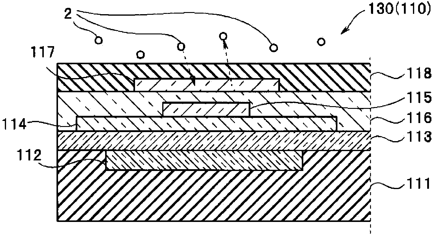
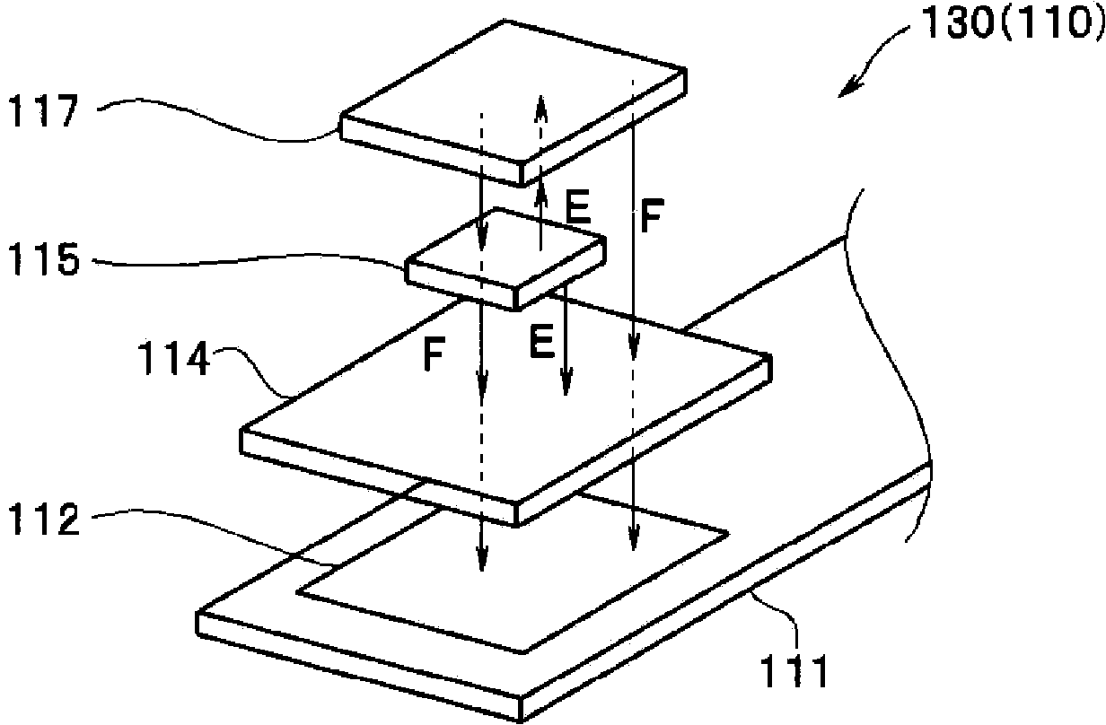
[0098] like Figure 8 As shown, on the detection substrate portion 11B of the sensing portion 10B of the fluorescence sensor 30B, in addition to the PD element 12 as the first photoelectric conversion element for detecting the fluorescence generated by the indicator 17, a detection LED chip 15L is also formed. The generated excitation light is directed to the PD element 12B as the second photoelectric conversion element. That is, the light receiving portion of the first PD element 12 is formed on the wall surface 22 of the through hole 21 of the detection substrate portion 11B, and the light receiving portion of the second PD element 12B is formed on the second main ...


PUM

PropertyMeasurementUnit
thicknessaaaaaaaaaa

Abstract

A fluorescent sensor (30) is provided with: a detection substrate section (11), wherein a PD element (12), which converts fluorescence into electric signals, is formed on a wall surface (22) of a through hole (21) that penetrates a first main surface (11SA) and a second main surface (11SB); an indicator (17), which is disposed inside of the through hole (21), and which generates fluorescence with intensity corresponding to the concentration of an analyte when the excitation light is received; a filter layer (14), which covers the PD element (12), passes through the fluorescence, and blocks the excitation light; a light blocking layer (18), which covers an opening of the through hole (21), said opening being in the first main surface (11SA), and which the analyte can pass through; and an LED chip (15), which covers a region just below the opening of the through hole (21), said opening being in the second main surface (11SB), and which generates the excitation light.

Description

technical field [0001] The present invention relates to a fluorescent sensor for measuring the concentration of an analyte in a liquid and a sensing system with the above-mentioned fluorescent sensor, in particular to a fluorescent sensor as a miniature fluorescence photometer made by using semiconductor manufacturing technology and MEMS technology and a fluorescent sensor with the above-mentioned fluorescent sensor. Induction system of sensors. Background technique [0002] Various analytical devices have been developed for measuring the concentration of an analyte, that is, a substance to be measured, in a liquid. For example, there is known a fluorophotometer that measures the concentration of an analyte by pouring a fluorochrome and a test solution containing an analyte into a transparent container, irradiating excitation light and measuring the intensity of fluorescence from the fluorochrome. The properties of the fluorochrome will change due to the presence of the ana...

Claims


Application Information

Patent Timeline
Patent Type & Authority Applications(China)
IPC IPC(8): G01N21/64
CPCG01N21/645G01N21/6428G01N21/77G01N2021/6434G01N2021/6469G01N2021/6471G01N2021/7753G01N2021/7786G01N2201/064
Inventor 太田亮松本淳
Owner TERUMO KK
Why Eureka
Try Eureka