Electric working machine
A working machine and electric technology, applied in the direction of DC motor reduction gear, electric motor/converter plug, harvester, etc., can solve the problem of not being able to brake quickly
- Summary
- Abstract
- Description
- Claims
- Application Information
AI Technical Summary
Problems solved by technology
Method used
Image
Examples
no. 1 example
[0040] Hereinafter, embodiments of the present invention will be described with reference to the drawings. In the drawings, the same reference numerals refer to the same elements, and detailed descriptions thereof will not be repeated. In addition, in this specification, front and back, left and right, and up and down directions will be described based on the directions shown in the drawings.
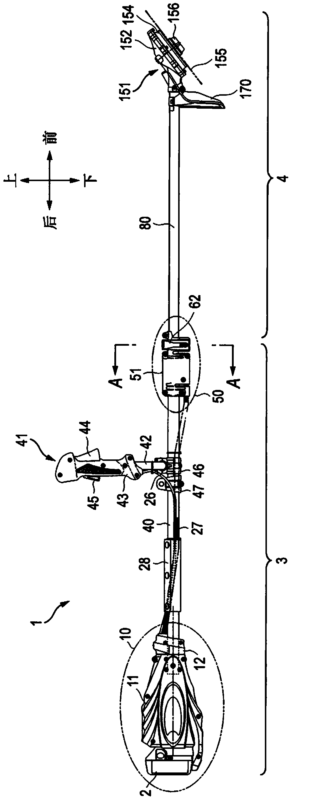
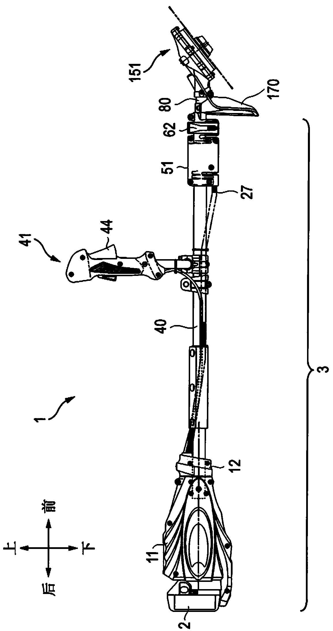
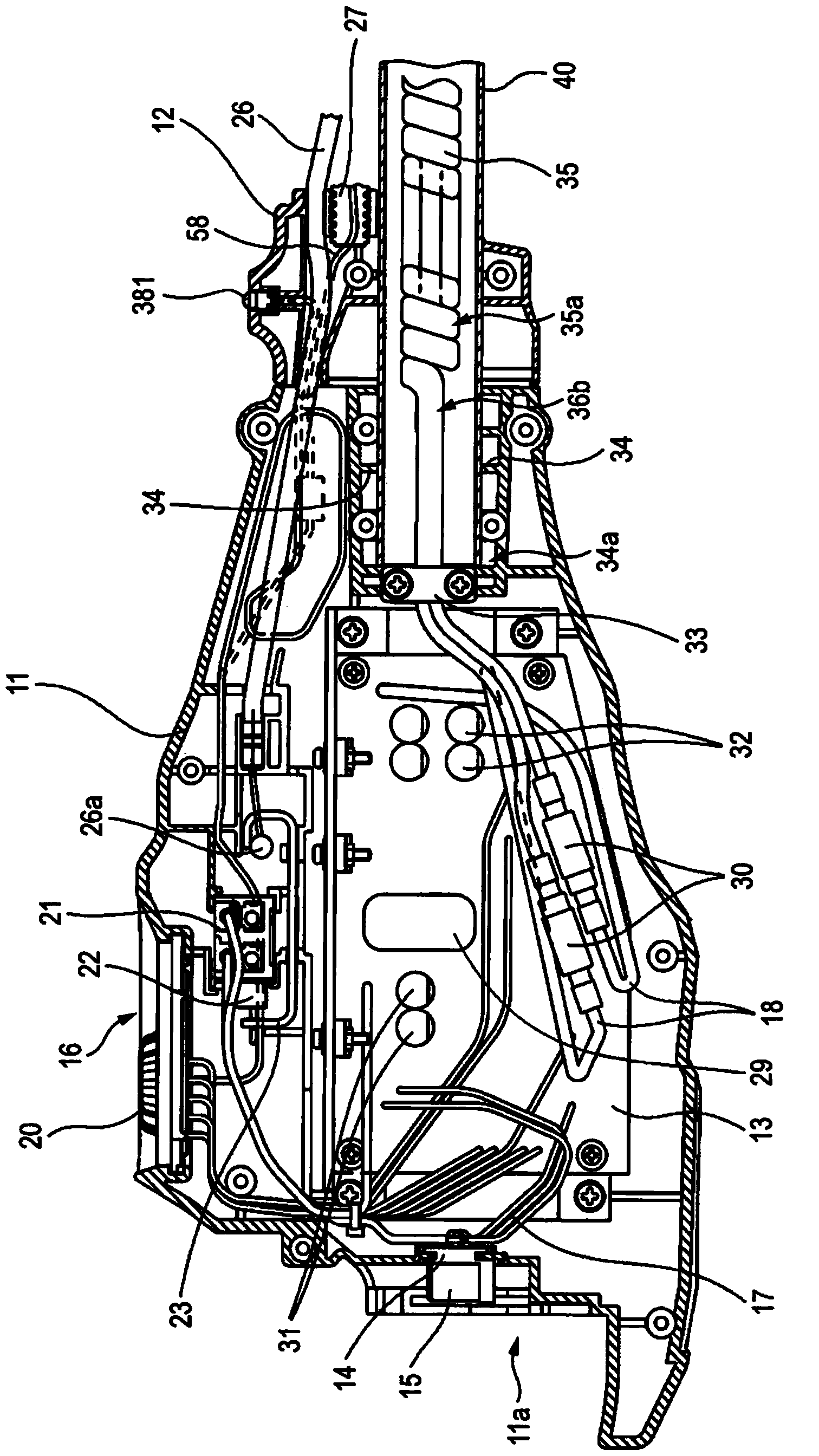
[0041] Such as figure 1 As shown, an electric bush cutter 1 as an example of an electric working machine includes: an operation unit 10 to which a battery pack 2 is attached; a retractable rod which is fixed to the vicinity of the front end of the operation unit 10; and a drive unit 151 to which is attached To the end of the rod; and the handle unit 41, which is fixed to the vicinity of the center of the rod in the front-rear direction. In the current embodiment, the contraction rod includes a fixed tube 40 and a movable tube 80. The movable tube 80 is connected to the front side of the ...
no. 2 example
[0081] In the following, we will refer to Picture 11 The circuit diagram according to the second embodiment of the present invention is described. The controller 301 according to the second embodiment is installed in image 3 On the circuit board 13 shown, the configuration or components other than the circuits mounted on the circuit board 13 are exactly the same as those described in the first embodiment. The controller 301 includes the same switch 21 as in the first embodiment, a main power switch circuit 214, a main power automatic stop circuit 203, a constant voltage circuit 207, a battery voltage detection circuit 235, a trigger detection circuit 240, and a microcomputer 211, and Therefore, repeated descriptions about its internal structure or behavior will be omitted. The output stop circuit 343 is mainly in accordance with the output stop circuit 243 of the first embodiment (see Figure 7 ) Operates in the same manner, that is, the output stop circuit 343 receives a sto...
PUM
 Abstract
Description
Claims
Application Information
 - R&D
- Intellectual Property
- Life Sciences
- Materials
- Tech Scout
- Unparalleled Data Quality
- Higher Quality Content
- 60% Fewer Hallucinations
Browse by: Latest US Patents, China's latest patents, Technical Efficacy Thesaurus, Application Domain, Technology Topic, Popular Technical Reports.
© 2025 PatSnap. All rights reserved.Legal|Privacy policy|Modern Slavery Act Transparency Statement|Sitemap|About US| Contact US: help@patsnap.com


