a condenser lens

A condensing lens and lens technology, applied in the field of condensing lenses, can solve the problems of reduced light output efficiency and light intensity at the center of the spot, increased mold difficulty, and reduced yield rate, etc. The effect of uniformity

Inactive Publication Date: 2017-01-25
FOSHAN INST SUN YAT SEN UNIV +1
View PDF7 Cites 3 Cited by
  • Summary
  • Abstract
  • Description
  • Claims
  • Application Information

AI Technical Summary

Problems solved by technology

However, it only considers the blocking of residual light, but ignores the reduction of light extraction efficiency and light intensity in the center of the spot caused by the elimination of residual light, and the sharp angle structure in the inner cavity will greatly increase the difficulty of mold injection and easily lead to a decrease in yield. Structure processing is difficult

Method used


Image

  • a condenser lens
  • a condenser lens
  • a condenser lens

Examples


Embodiment 1

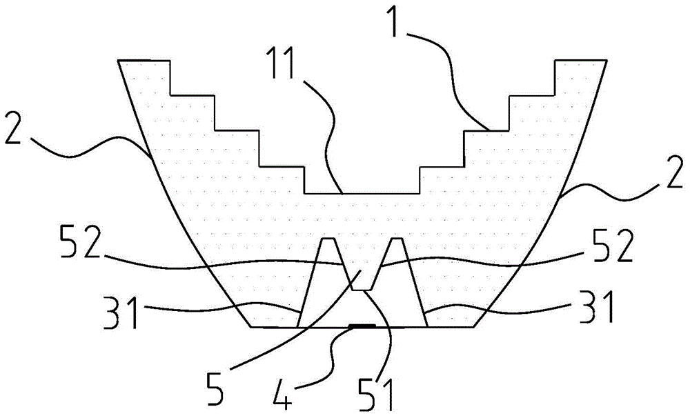
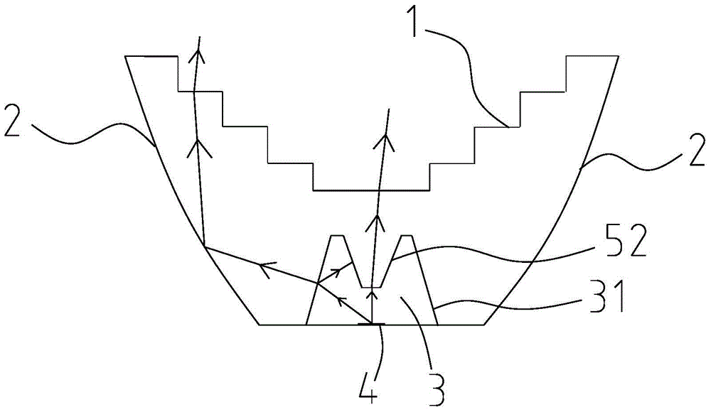
[0040] Refer to attached figure 1 to attach Figure 4 As shown, a condenser lens, the lens is a cup-shaped structure, and the inner diameter of the cup-shaped structure gradually decreases from the top to the bottom. The lens includes a light exit surface 1, a side curved surface 2 and a light incident surface, the light exit surface 1 is located at the top of the lens, one side of the side curved surface 2 is connected to the light exit surface 1, and the other side of the side curved surface 2 is connected to the light exit surface. The light incident surface is connected, and the inner wall of the side curved surface 2 is a total reflection surface. The light incident surface is located at the bottom of the lens and is recessed in the lens to form an inner cavity 3 for accommodating the light source, and the inner cavity 3 covers the light source 4 . The bottom of the cup-shaped structure is a circular surface, and the light source is a linear LED light-emitting element l...

Embodiment 2

[0048] The difference between this embodiment and Embodiment 1 is that: the second light incident surface is a convex surface 51a that is convex relative to the top of the lens, that is, the convex surface is convex downwards, refer to the attached Figure 6 As shown, the bottom surface 11a of the light-emitting surface is flat, and the convex surface 51a is combined with the bottom surface 11a of the light-emitting surface to gather and emit the light in the central part of the light source without being scattered or lost, thus obtaining more High central light intensity. The condenser lens of this embodiment can achieve the same effect of blocking stray light.

[0049] Other technical features are the same as those in Embodiment 1, and can achieve the same technical effect, and will not be described in detail here.

Embodiment 3

[0051] The difference between this embodiment and Embodiment 1 is that the second light-incident surface is a convex surface 51b that is raised relative to the bottom surface of the lens, that is, the convex surface is raised upwards, and the bottom surface 11b of the light-emitting surface is raised upwards relative to the bottom surface of the lens. surface, see attached Figure 7 As shown, the light projected onto the second light incident surface is refracted into the lens through the convex surface 51b, and emerges from the bottom surface 11b of the light exit surface. The convex surface 51b is combined with the bottom surface 11b of the light exit surface to achieve a certain focusing effect, which can The light in the central part of the light source is gathered and emitted without being scattered or lost, thus obtaining a higher and brighter central light intensity. The condenser lens of this embodiment can achieve the same effect of blocking stray light.

[0052] Oth...


PUM


Abstract

The invention discloses a condensing lens which comprises a light outlet face, a lateral curved face and a light inlet face. The light inlet face is arranged at the bottom of the condensing lens and is concavely arranged in the condensing lens to form an inner cavity for accommodating a light source. A step protruding to one side of the light source is arranged at the top of the inner cavity, the lateral wall of the inner cavity serves as a first light inlet face, and all points on the step are arranged above a straight line formed by the connection between one end of the top of the inner cavity and the relative end of the light source. Light reflected by a first light emitting face can be projected to the surface of the step and can be scattered or absorbed by the surface of the step. The step can prevent the reflected light from entering the condensing lens from the other side of the inner cavity, so that no miscellaneous aureole and no miscellaneous halo are generated around light spots projected by the condensing lens, and the evenness and the visual attractiveness of the light spots are greatly improved. Meanwhile, light generated by the condensing lens can be gathered at the central light strength position, the central light strength and the brightness of the light spots are improved, and the light outlet efficiency is high. The condensing lens is simple in structure, strong in workability and easy to produce.

Description

technical field [0001] The invention belongs to the field of LED light source lighting, and in particular relates to a condenser lens. Background technique [0002] LED lamps have gradually replaced traditional lamps and are widely used due to their many advantages such as energy saving, environmental protection, long life, and high controllability. In order to increase the light extraction efficiency and light intensity of the LED lamps, some people in the prior art cover the LED light source with an optical lens. The light emitted by the LED light source is adjusted and arranged through the lens to meet different visual needs. It has been widely used in public places such as stages, bars, and meeting rooms. However, there is often a heterocyclic ring around the main spot produced by the LED lens. When the power of the light source is high, the light emitted by the LED light source enters the lens through the side wall of the lens cavity, and part of the light will be refl...

Claims


Application Information

Patent Timeline
Patent Type & Authority Patents(China)
IPC IPC(8): F21V5/04F21Y115/10
Inventor 朱道勇罗滔王樱雪
Owner FOSHAN INST SUN YAT SEN UNIV
Why Eureka
Try Eureka