
Source stirring electromagnetic reverberation chamber and stirring method thereof

A technology of electromagnetic reverberation chamber and stirring method, which is applied in the direction of measuring electricity, measuring electrical variables, measuring devices, etc., can solve the problems of low space utilization rate and low field strength capability of mechanical stirring reverberation chamber, and improve the test efficiency. , high field strength, the effect of improving flexibility

Inactive Publication Date: 2014-11-05
陕西海泰电子有限责任公司
View PDF8 Cites 16 Cited by
  • Summary
  • Abstract
  • Description
  • Claims
  • Application Information

AI Technical Summary

Problems solved by technology

[0007] In order to solve the technical problems of low utilization rate of the internal space of the mechanically stirred reverberation chamber and low ability to generate field strength per unit power, the present invention provides a source-stirred electromagnetic reverberation chamber and its stirring method, which can be used in the electromagnetic reverberation chamber Realize the statistically uniform and statistically isotropic electromagnetic field test environment, which can be used as a technical way to realize the source stirring electromagnetic reverberation chamber

Method used


Image

  • Source stirring electromagnetic reverberation chamber and stirring method thereof

Examples


Embodiment Construction

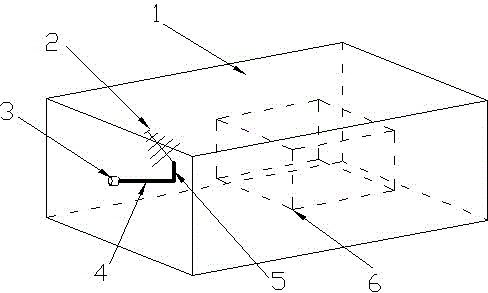
[0035] see figure 1 , a source stirring electromagnetic reverberation chamber, including an electromagnetic shielding chamber 1, also includes a source stirring assembly arranged on the side wall of the electromagnetic shielding chamber 1; the source stirring assembly includes a stepping motor 3, a rotating shaft connected to the stepping motor 3 4. An extension arm 5 arranged on the rotating shaft 4 and a transmitting antenna 2 arranged on the extension arm 5; at least one source stirring assembly.

[0036] A stirring method for a source stirring reverberation chamber, comprising the following steps:

[0037] 1) Install the transmitting antenna 2 on one end of the extension arm 5, change the rotation radius of the transmitting antenna 2 relative to the rotation axis 4 by adjusting the installation position of the extension arm 5 on the rotation axis 4, and record the initial position of the transmitting antenna 2;

[0038] 2) Take the installation position of the transmittin...


PUM


Abstract

Disclosed are a source stirring electromagnetic reverberation chamber and a stirring method thereof. The reverberation chamber includes an electromagnetic shielding chamber, a source stirring device installed on the side wall of the electromagnetic shielding chamber, and the source stirring method used for describing installation, motion and control method of an transmitting antenna. Simultaneous change of the position and polarization direction of the transmitting antenna is realized through control of a rotating shaft to rotate. A drive device of the rotating shaft is installed at the outer side of the reverberation chamber and the rotating shaft which is installed on the inner wall of the reverberation chamber is driven to rotate through a changeover mechanism. The reverberation chamber realizes field uniformity in the reverberation chamber through rotation of a single antenna so that space utilization rate in the reverberation chamber is effectively improved and a source stirring reverberation chamber of the same volume can realize a larger test area; relative to an EUT of the same size, a source stirring reverberation chamber which is smaller in volume can be designed so that generation of high field intensity is better facilitated; and the reverberation chamber is also applicable to a condition in which a plurality of transmitting antennae are configured in a reverberation chamber to carry out source stirring.

Description

technical field [0001] The invention relates to the field of electromagnetic compatibility experiments and tests, in particular to a source-stirred electromagnetic reverberation chamber and a stirring method thereof. Background technique [0002] Existing electromagnetic reverberation chambers are generally mechanically stirred reverberation chambers, and the electromagnetic boundary conditions inside the reverberation chamber are changed by changing the state of the mechanical stirrer, thereby achieving the purpose of changing the electromagnetic field distribution inside the reverberation chamber. Due to the multiple reflections on the walls of the reverberation chamber and the "stirring" effect of the stirrer, the electromagnetic environment inside the reverberation chamber presents a statistically uniform and isotropic feature, that is, during the stirring process of the stirrer, any part of the test area The phase and amplitude of the electromagnetic field at the positi...

Claims


Application Information

Patent Timeline
Patent Type & Authority Applications(China)
IPC IPC(8): G01R31/00
Inventor 郭恩全汤兴刚肖宁许策
Owner 陕西海泰电子有限责任公司
Learn More