Speed regulating control strategy for sensorless permanent magnet synchronous motor

A permanent magnet synchronous motor and control strategy technology, applied in the direction of single motor speed/torque control, electronic commutator, etc., can solve the problems of low estimation accuracy, large resistance value, affecting the performance of the control system, etc.

Inactive Publication Date: 2014-11-05
UNIV OF JINAN
View PDF2 Cites 19 Cited by
  • Summary
  • Abstract
  • Description
  • Claims
  • Application Information

AI Technical Summary

Problems solved by technology

However, the traditional sliding mode observer uses the signum function as the switching function, which has obvious chattering phenomenon, and the calculation of the rotational speed by the direct differential method w

Method used


Image

  • Speed regulating control strategy for sensorless permanent magnet synchronous motor
  • Speed regulating control strategy for sensorless permanent magnet synchronous motor
  • Speed regulating control strategy for sensorless permanent magnet synchronous motor

Examples


Embodiment Construction

[0045] The present invention will be further described below in conjunction with the drawings.

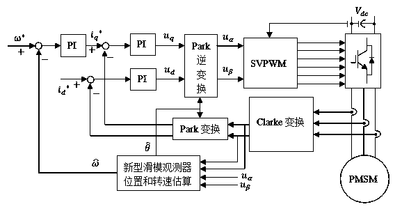
[0046] figure 1 The principle block diagram of the sensorless permanent magnet synchronous motor speed control system.

[0047] The invention discloses a sensorless permanent magnet synchronous motor speed regulation control strategy, which includes the following specific steps.

[0048] The three-phase current ia, ib and ic of the permanent magnet synchronous motor are detected by the current sensor, and the current in the αβ coordinate system is obtained through Clarke transformation , , And get the current id and iq in the dq coordinate system after Park transformation.

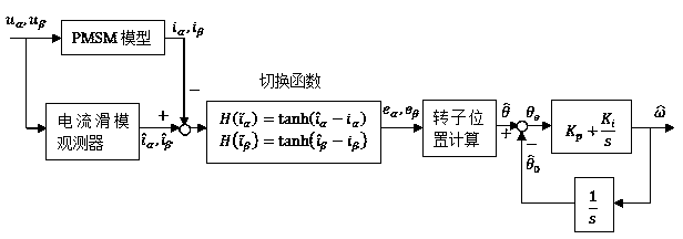
[0049] According to the mathematical model of the permanent magnet synchronous motor in the αβ two-phase static coordinate system, the Sliding Mode Current Observer is designed, such as figure 2 Shown.

[0050] The hyperbolic tangent function is used as the switching function.

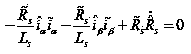
[0051] Select the sliding surface,...


PUM


Abstract

The invention belongs to the field of control over a permanent magnet synchronous motor, and relates to a speed regulating control strategy for a sensorless permanent magnet synchronous motor. The speed regulating control strategy is characterized in that a three-phase current of the permanent magnet synchronous motor is detected, the current under an alpha and beta coordinate system is obtained through Clarke conversion, and the current under the dq coordinate system is obtained through Park conversion; a sliding-mode observer is designed according to a mathematic model of the permanent magnet synchronous motor under the alpha and beta two-phase static coordinate system; a hyperbolic tangent function is used as a switching function; a sliding-mode face is selected; the estimation value of the rotor position is obtained through counter electromotive force; a speed estimator is adopted for estimating the speed; a Lyapunov function is selected, and an adaptive law is obtained through the stability condition; According to the speed regulating control strategy, the structural switching discontinuity is relieved, the buffeting is obviously weakened, the rapidness, the robustness and the dynamic performance are improved, when an error exists in the estimation value of the rotor position, the speed estimation error is made to be within the controllable range, and the rotating speed estimation precision is improved.

Description

Technical field [0001] The invention relates to the field of permanent magnet synchronous motor control, in particular to a sensorless permanent magnet synchronous motor speed regulation control strategy. Background technique [0002] The speed regulation performance of the motor affects industrial production and energy efficiency. Permanent magnet synchronous motors are widely used in electric vehicles, aerospace navigation, household appliances, electric vehicles, aerospace navigation, household appliances, etc. due to their high power density, high torque ratio, high efficiency, high reliability, small loss, small size, light weight and simple structure. Trackless locomotives and other fields. The precise control of a permanent magnet synchronous motor requires the position and speed information of the rotor. In its speed control system, in order to obtain accurate speed information, it is usually necessary to install a mechanical sensor, which increases the size of the motor...

Claims


Application Information

Patent Timeline
IPC IPC(8): H02P6/08H02P6/18
Inventor 韩飞飞王中华韩统一顾杰
Owner UNIV OF JINAN
Why Eureka
Try Eureka