
Method for reducing power consumption of circuit in DMR (Digital Mobile Radio) terminal and circuit implementing same

A circuit and terminal technology, applied in the direction of power management, electrical components, energy consumption reduction, etc., can solve problems such as complexity and increased circuit power consumption, and achieve the effects of reducing power consumption, reducing average power consumption, and prolonging standby life

Inactive Publication Date: 2014-11-05
KIRISUN COMM
View PDF2 Cites 10 Cited by
  • Summary
  • Abstract
  • Description
  • Claims
  • Application Information

AI Technical Summary

Problems solved by technology

[0002] DMR (Digital Mobile Radio) terminal is a new type of digital handheld wireless terminal (commonly known as DMR digital walkie-talkie) that complies with the DMR technical specification of the European Telecommunications Standards Institute (ETSI). Powerful, of course, the baseband and radio frequency circuits are more complex than traditional analog walkie-talkies, using high-speed processors and large-capacity memory, the power consumption of the circuit is also greatly increased, which brings greater challenges to the design of improving battery support time

Method used


Image

  • Method for reducing power consumption of circuit in DMR (Digital Mobile Radio) terminal and circuit implementing same
  • Method for reducing power consumption of circuit in DMR (Digital Mobile Radio) terminal and circuit implementing same
  • Method for reducing power consumption of circuit in DMR (Digital Mobile Radio) terminal and circuit implementing same

Examples


Embodiment

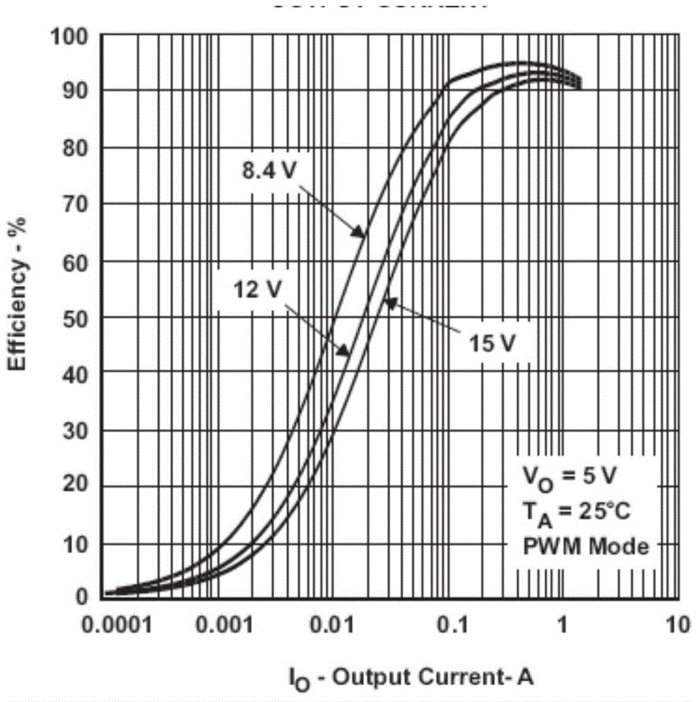
[0047] Taking the parameter curve provided by a typical DCDC power step-down converter chip manual as an example, under the same load current, compare the conversion efficiency difference between the PWM and PFM operating modes.

[0048] The following is a set of data curves of the power supply circuit under the condition of an input voltage of 8.4V and an output voltage of 5.0V.

[0049] image 3 is the efficiency curve of the power converter working in PWM mode.

[0050] Figure 4 is the efficiency curve of the power converter working in PFM mode.

[0051] Under the condition of 0.1A current, the conversion efficiency in PWM mode is 90%; the conversion efficiency in PFM mode is 95%, and the conversion efficiency can be increased by 5%.

[0052] Under the condition of 20mA current, the conversion efficiency in PWM mode is 67%; the conversion efficiency in PFM mode is 92%, and the conversion efficiency can be increased by 25%.

[0053] see Figure 5 As shown, the method f...


PUM


Abstract

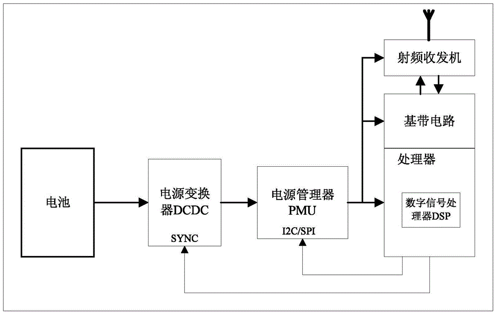
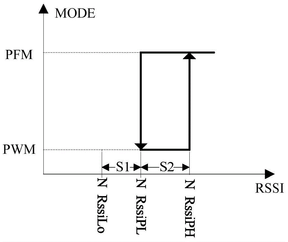
The invention provides a method for reducing the power consumption of a circuit in a DMR (Digital Mobile Radio) terminal and the circuit implementing the method. The method comprises the following steps: monitoring the field strength data of a radio-frequency signal by a digital signal processor DSP of the terminal; if the field strength data value of the radio-frequency signal exceeds the upper limit value of a power-saving field strength threshold, outputting a control signal by the processor, and converting the operating mode of a power converter into a PFM (Pulse Frequency Modulte) mode; if the field strength data value of the radio-frequency signal is lower than the lower limit value of the power-saving field strength threshold, outputting the control signal by the processor, and converting the operating mode of the power converter into a PWM (Pulse Width Modulte) mode. According to the method for reducing the power consumption of the circuit in the DMR terminal provided by the invention, independent of the dormancy awakening power-saving mechanism of a system base station, each terminal can dynamically adjust the power-supply efficiency at a specific mode, and the battery consumption can be saved to a greater degree, so that average power consumption of the circuit of the DMR terminal is effectively reduced, and the standby durance time of a DMR terminal battery is prolonged; meanwhile, the electromagnetic environment pollution of wireless communication equipment is also reduced.

Description

technical field [0001] The invention relates to the technical field of wireless communication, in particular to a method for reducing circuit power consumption of a DMR terminal and a circuit for realizing it. Background technique [0002] DMR (Digital Mobile Radio) terminal is a new type of digital handheld wireless terminal (commonly known as DMR digital walkie-talkie) that conforms to the DMR technical specification of the European Telecommunications Standards Institute (ETSI). Powerful, of course, the baseband and radio frequency circuits are more complex than traditional analog walkie-talkies, using high-speed processors and large-capacity memory, the power consumption of the circuit is also greatly increased, which brings greater challenges to the design of improving battery support time. [0003] Handheld wireless terminals are generally powered by large-capacity rechargeable batteries, which have high requirements for battery capacity, standby time and working time. ...

Claims


Application Information

Patent Timeline
IPC IPC(8): H04W52/02
CPCY02D30/70
Inventor 童奉群付文良
Owner KIRISUN COMM
Learn More