Automatic feeding plate slot milling machine with magnetic sucking cup

A technology of automatic feeding and magnetic sucker, which is applied in the direction of milling machine equipment, milling machine equipment details, metal processing equipment, etc., can solve the problem of difficult control of the width and depth of the oil storage groove, affecting the precision of the inner hole of the shaft sleeve, and low turning efficiency, etc. question

Active Publication Date: 2014-11-12
ZHEJIANG SF OILLESS BEARING
View PDF5 Cites 0 Cited by
  • Summary
  • Abstract
  • Description
  • Claims
  • Application Information

AI Technical Summary

Problems solved by technology

When in use, lubricating oil or grease is added to the oil storage groove to lubricate the friction pair, but the efficiency of such turning is very low, and the width and depth of the oil storage groove are difficult to control, and in the oil storage groove or There will be burrs in the groove of the oil storage groove, which will affect the accuracy of the inner hole of the shaft sleeve

Method used


Image

  • Automatic feeding plate slot milling machine with magnetic sucking cup
  • Automatic feeding plate slot milling machine with magnetic sucking cup
  • Automatic feeding plate slot milling machine with magnetic sucking cup

Examples


Embodiment Construction

[0022] The present invention will be further described below in conjunction with the accompanying drawings and specific embodiments.

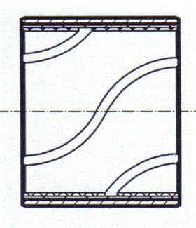
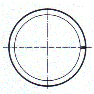
[0023] Figure 5 , Image 6 Figure 7 It is a schematic diagram of the structure of the magnetic sucker automatic feeding plate milling machine. As can be seen from the figure, it includes a frame 1, a table panel 2 is fixed on the frame 1, a slideway seat 3 is fixed at the left and right ends of the table panel 2, and two parallel parallel bars are fixed on the slideway seat 3. Circular slideways 4 of equal height, each slideway 4 is covered with a bearing seat 5, a sliding bearing 6 is fixed in the bearing seat 5, an upper plate 7 is fixed on the bearing seat 5, and a fixed upper plate 7 is fixed on the upper plate 7 Adjustment panel 8 is arranged, and plane electromagnetic chuck 9 is fixed on the adjustment panel 8, and this electromagnetic chuck 9 is identical with the electromagnetic chuck on the surface grinder, and magnetism can be pr...


PUM


Abstract

The invention discloses an automatic feeding plate slot milling machine with a magnetic sucking cup. The automatic feeding plate slot milling machine comprises a machine frame, and the machine frame is fixedly connected with a deck plate. The automatic feeding plate slot milling machine with the magnetic sucking cup is characterized in that the left end and the right end of the deck plate are respectively and fixedly connected with a slide rail base, the slide rail bases are fixedly connected with two parallel slide rails of the same height, each slide rail is sleeved with a bearing pedestal, a sliding bearing is fixed in each bearing pedestal, an upper plate is fixed on the bearing pedestals, an adjusting panel is fixed on the upper plate, a plane electromagnetic sucking cup is fixed on the adjusting panel, the electromagnetic sucking cup is connected with a piston rod of an oil cylinder at one end of the corresponding bearing pedestal, the piston rod is telescopic to drive the electromagnetic sucking cup to move left and right, the front side and the rear side of the electromagnetic sucking cup on the deck plate are respectively and fixedly connected with a cutter base, a cutter shaft is mounted between the two cutter bases, saw blade milling cutters are mounted on the cutter shaft above the electromagnetic sucking cup, one end of the cutter shaft is driven by a motor to rotate, and the milling cutters conduct groove milling on plates which are attracted on the electromagnetic sucking cup. The production efficiency is 5-8 times the efficiency for turning oil storage grooves in a lathe originally.

Description

technical field [0001] The invention relates to equipment for machining mechanical parts, in particular to a milling machine for automatically feeding a magnetic sucker plate used for machining spiral oil grooves in inner holes of sleeve-type sliding bearings. Background technique [0002] In recent years, there have been some sleeve-type sliding bearings made of composite plates by rolling. They use steel plates as the base material, and then sinter a copper alloy layer on the surface of the base material to make bimetallic plates. Sleeve type sliding bearings. Steel plates are also used as the base material, and then a spherical copper alloy powder layer is sintered on the surface of the base material, and a wear-resistant plastic layer is laid on the copper alloy powder layer and sintered into a three-layer composite plate such as figure 1 As shown, the three-layer composite sheet is rolled into a sleeve type sliding bearing. In order to further improve the wear...

Claims


Application Information

Patent Timeline
Patent Type & Authority Applications(China)
IPC IPC(8): B23C3/28B23C9/00
Inventor 沈之明
Owner ZHEJIANG SF OILLESS BEARING
Why Eureka
Try Eureka