Well drilling pressurizing speed-up device

A speed booster and supercharger technology, which is applied to drilling equipment, liquid/gas jet drilling, and driving devices for drilling in boreholes. It can solve the problems of increasing processing difficulty, reducing reliability, and poor safety. Good speed effect, slow solution speed, and reliable performance

Inactive Publication Date: 2014-11-12
CHINA UNIV OF PETROLEUM (EAST CHINA)
View PDF5 Cites 2 Cited by
  • Summary
  • Abstract
  • Description
  • Claims
  • Application Information

AI Technical Summary

Problems solved by technology

[0003] Surface full pressurization and ground partial displacement pressurization first appeared in the United States in the 1970s and 1980s. The disadvantages of this technology are: first, the entire pressurized pipeline has high sealing requirements, and the on-site application requires corresponding drilling systems and equipment. The matching is poor in safety; secondly, the pressure loss of the mud flowing in the pipeline is large, the energy efficiency ratio is poor, and the boosting capacity is limited
For the booster technology of downhole boosters, two kinds of boosters, static pressure type and jet type, have appeared successively. The disadvantages of this technology are: there is a complex reversing valve system and more flow channels, and the structure is complicated and petite. , which reduces the reliability and increases the processing difficulty
There is also a turbine centrifugal downhole supercharger. The disadvantage of this technology is: due to the high speed of the turbine, a special reducer needs to be designed to match it; in order to meet the necessary pressure requirements, a multi-stage centrifugal pump must be used, so that the system is relatively Complexity, which reduces the reliability of the system
The disadvantages of this structure of the slope type downhole booster are: in the reversing mechanism, the two contact surfaces are severely worn, and the performance requirements for the return spring are relatively high. The bearing produces a large load shock, which reduces its life

Method used


Image

  • Well drilling pressurizing speed-up device
  • Well drilling pressurizing speed-up device
  • Well drilling pressurizing speed-up device

Examples


Embodiment Construction

[0016] The structure and implementation of the present invention will be described in detail below in conjunction with the accompanying drawings.

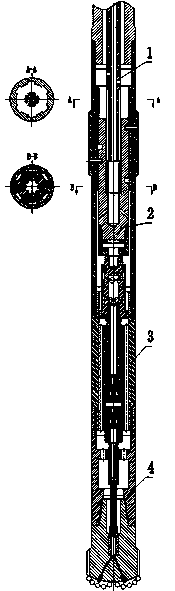
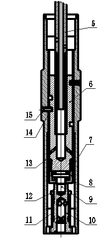
[0017] First, connect the power mechanism, reversing and filtering mechanism, booster system and booster bit system through threads to form the entire drilling booster (see figure 1 ). The outer surface of the rotating mandrel (6) is processed with double helical grooves, one end of the pin shaft (15) slides relatively in the helical groove, and the other end is fixedly installed on the cylinder (13); the screw motor output shaft (5) and the rotating core The shafts are matched by splines, and the rotation of the motor drives the rotating mandrel to rotate together. Since the pin shaft is fixed, the rotating mandrel processed with spiral grooves must also move up and down while rotating; the rotating mandrel and the filter cylinder (10) pass the thrust The bearing (8) and the connecting bolt (9) are connected, and the filter cylin...


PUM


Abstract

The invention provides a well drilling pressurizing speed-up device. The well drilling pressurizing speed-up device is used for increasing well drilling speed during petroleum drilling. The well drilling pressurizing speed-up device comprises a power mechanism, a reversing and filtering mechanism, a pressurizing system and a pressurizer drilling bit system. The output shaft of a screw motor is provided with an external spline and matched with a rotating core shaft with an internal spline to rotate together; the outer portion of the rotating core shaft is provided with two spiral grooves, and the rotating core shaft, a pin shaft, a thrust bearing, a connecting bolt, a filter barrel and the like compose an outer spiral groove-type reversing mechanism. Under the action of the outer spiral groove-type reversing mechanism, the rotating movement of the screw motor is converted into the linear reciprocating movement of a plunger, a part of filtered liquid is pressurized into a ultrahigh pressure, and the ultrahigh-pressure liquid flows towards an ultrahigh-pressure spray nozzle inside a drilling bit through a discharge valve and an ultrahigh-pressure flow channel to achieve the aim of cutting rock and accelerating drilling.

Description

technical field [0001] The invention relates to a drilling supercharging speed increaser, which is used for increasing the drilling speed during oil drilling. Background technique [0002] Since the 1990s, as the proportion of deep wells and ultra-deep wells in oilfields has increased, the formations encountered in drilling have become harder and harder, the downhole environment has become more and more complex, and the problems encountered in the drilling process have also become more and more serious. For example, the drilling speed has dropped significantly, and the bottom hole fluid flow has almost no rock-breaking ability due to pressure loss along the way, etc. Therefore, in the modern drilling industry, how to increase the drilling speed, shorten the drilling cycle, and reduce the drilling cost has attracted great attention from researchers at home and abroad, and a lot of research has been carried out on this. The development of drilling supercharging at home and ab...

Claims


Application Information

Patent Timeline
Patent Type & Authority Applications(China)
IPC IPC(8): E21B7/18E21B4/02
Inventor 赵军友徐晓娜徐依吉邹俊艳刘祥猛张蕊蕊束奇张振国王秀会万法伟王雷兰凯
Owner CHINA UNIV OF PETROLEUM (EAST CHINA)
Why Eureka
Try Eureka