
Transformer secondary winding zero current detection circuit for led drive power supply

A technology of zero current detection and secondary winding, applied in the direction of measuring current/voltage, measuring electrical variables, instruments, etc., can solve the problem of poor output constant current effect of LED drive power supply, change of load adjustment rate and linear adjustment rate of LED drive power supply Poor and other problems, to achieve a good output constant current effect, reduce the effect of delay

Active Publication Date: 2017-04-05
深圳天源中芯半导体有限公司
View PDF7 Cites 0 Cited by
  • Summary
  • Abstract
  • Description
  • Claims
  • Application Information

AI Technical Summary

Problems solved by technology

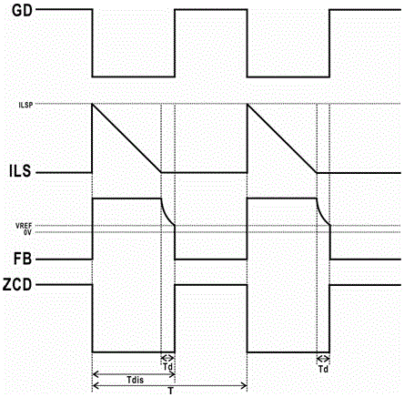
[0006] The traditional transformer secondary winding current zero-crossing detection circuit has the following disadvantages: there is a large delay between the moment when the secondary winding current crosses zero and the zero-current detection signal ZCD, so the zero-current detection signal ZCD cannot accurately reflect the secondary winding current of the transformer. The information of the winding current zero crossing time will make the output constant current effect of the LED drive power worse, and it will also make the load regulation and linear regulation of the LED drive power worse.
In the design of LED drive power supply that pays attention to current accuracy and adjustment rate characteristics, this traditional transformer secondary winding current zero-crossing detection technology has more and more limitations.

Method used


Image

  • Transformer secondary winding zero current detection circuit for led drive power supply
  • Transformer secondary winding zero current detection circuit for led drive power supply
  • Transformer secondary winding zero current detection circuit for led drive power supply

Examples


Embodiment 1

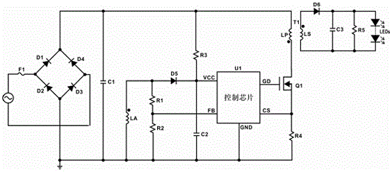
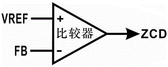
[0023] The invention solves the problem of excessive delay between the zero-crossing moment of the secondary winding current and the zero-current detection signal in the traditional transformer secondary winding zero-current detection technology, and provides a transformer secondary winding zero-current detection which solves the problem circuit. The zero-current detection signal is triggered by detecting the falling edge of the voltage across the secondary winding of the transformer, which greatly reduces the delay between the zero-crossing moment of the secondary winding current and the zero-current detection signal ZCD, effectively solving the traditional In the detection technology, the delay between the secondary winding current zero-crossing moment and the zero-current detection signal is too large, so that the zero-current detection signal ZCD can accurately reflect the information of the transformer secondary winding current zero-crossing moment.

[0024] Such as ima...


PUM


Abstract

The invention discloses a transformer secondary winding zero current detecting circuit used for an LED driving power source. The zero current detecting circuit comprises a transformer auxiliary winding unit, a resistor voltage divider unit, a negative edge detecting unit, a current sampling unit, a constant-current control unit and a logic and driving unit. The transformer auxiliary winding unit is used for sampling voltages of the two ends of a transformer secondary winding, the resistor voltage divider unit is used for dividing the sampled voltages and inputting the sampled voltages into a control chip, and the negative edge detecting unit is used for performing negative edge detecting on the waveform of the input voltage and generating a zero current detecting signal. The current sampling unit is used for sampling peak value currents of a transformer primary winding, the constant-current control unit is used for performing constant-current control over output currents output by the LED driving power source, and the logic and driving unit is used for performing logic control over output signals of the constant-current control unit, then driving a power switch tube and controlling the negative edge detecting unit. The LED driving power source has a very good effect of outputting constant currents, and meanwhile an ideal load regulation and linear regulation can be achieved.

Description

technical field [0001] The invention relates to a zero-current detection circuit, in particular to a zero-current detection circuit for a transformer secondary winding of an LED drive power supply. Background technique [0002] In the flyback LED constant current drive circuit, the primary side feedback control method is widely used to realize the constant current control of the output current. The control mode of the primary side feedback In order to realize the constant current control of the output current, in addition to accurately sampling the peak current of the primary winding of the transformer, it is also necessary to accurately detect the moment when the current of the secondary winding of the transformer crosses zero. [0003] In terms of detecting the zero-crossing moment of the secondary winding current of the transformer, the traditional solution is to use the auxiliary winding of the transformer to sample the voltage of the secondary winding of the transformer...

Claims


Application Information

Patent Timeline
Patent Type & Authority Patents(China)
IPC IPC(8): G01R19/175
Inventor 黄钦阳张明明邓小兵
Owner 深圳天源中芯半导体有限公司
Learn More