Grippers, twisting heads and twisting devices

A twisting and gripping technology, used in textiles and papermaking, electrical components, cable/conductor manufacturing, etc., can solve the problems of high cost, high weight, unadjustable wire end holding force, and achieve the effect of compact layout

Inactive Publication Date: 2018-11-09
SCHLEUNIGER HLDG
View PDF8 Cites 0 Cited by
  • Summary
  • Abstract
  • Description
  • Claims
  • Application Information

AI Technical Summary

Problems solved by technology

[0009] All solutions known in the prior art have in common that they are mechanically expensive and have a high weight
As a result, twisting devices are expensive and drive requirements are high
Also, the holding force for the wire ends is not adjustable

Method used


Image

  • Grippers, twisting heads and twisting devices
  • Grippers, twisting heads and twisting devices
  • Grippers, twisting heads and twisting devices

Examples


Embodiment Construction

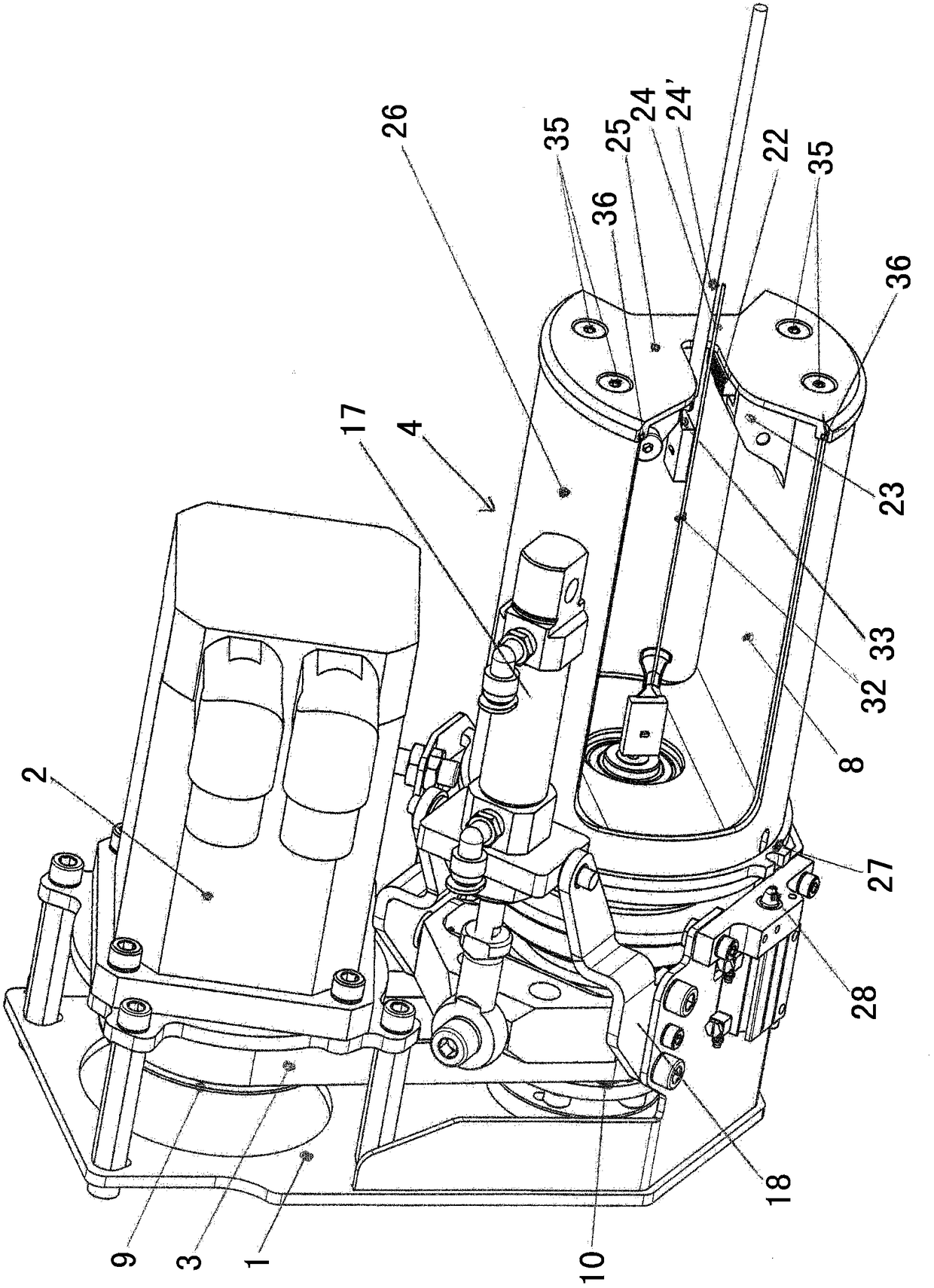
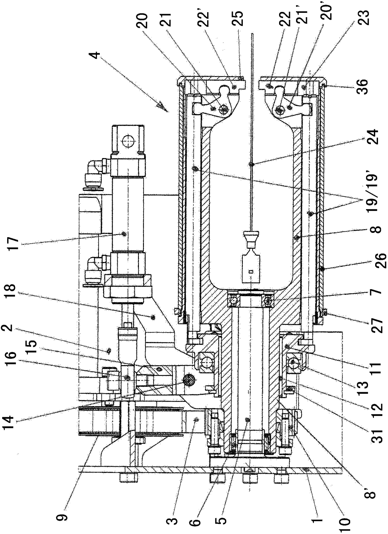
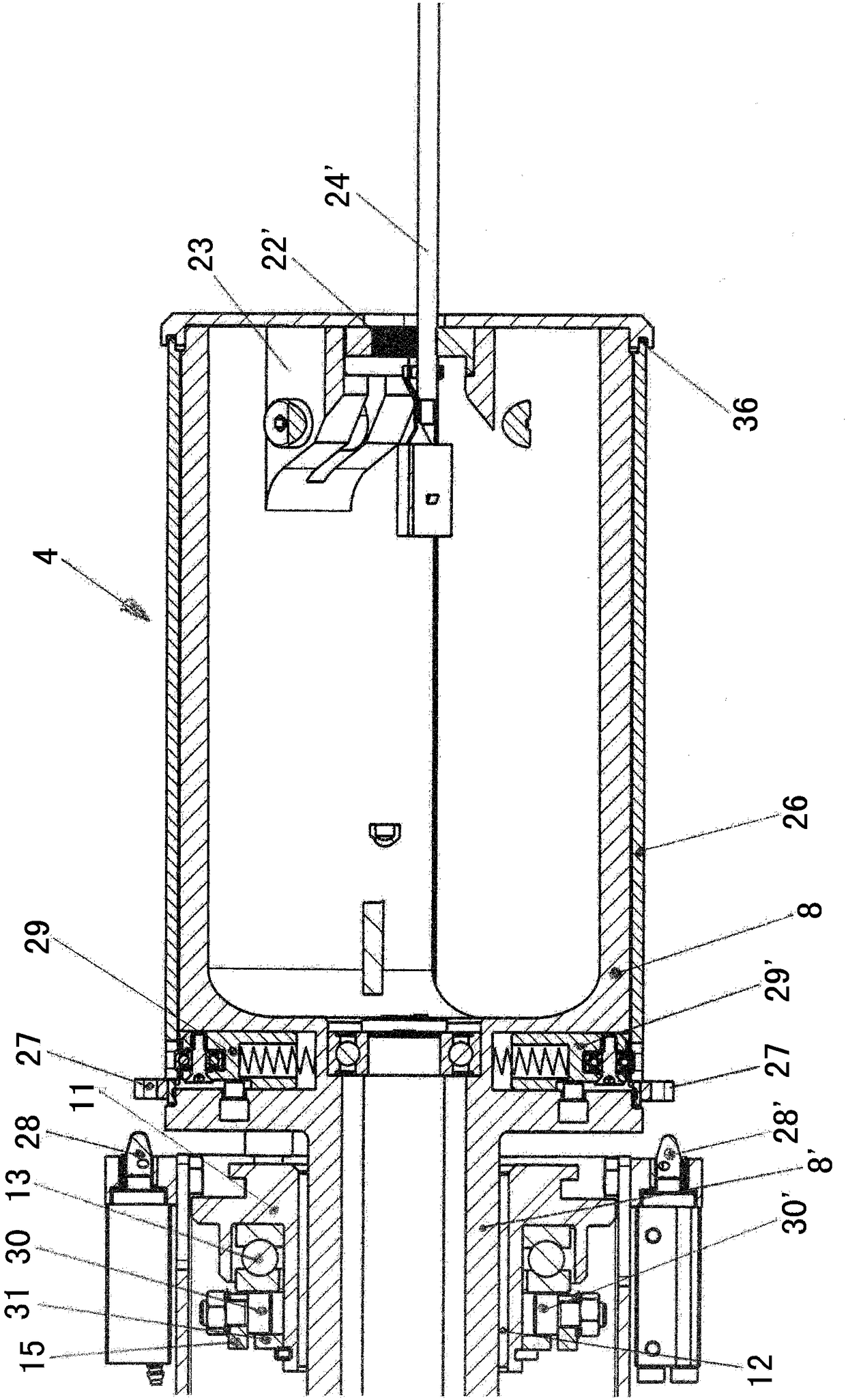
[0034] exist Figure 1 to Figure 4 In the illustrated embodiment shown, the twisting device according to the invention consists of a base 1 on which at least one drive motor 2, preferably a servo drive, for the twisting head 4 is mounted. The drive motor 2 drives the twisting head 4 via, for example, a drive belt 3 (preferably a toothed belt), the twisting head has an actual gripper comprising a plurality of structural components (see in particular for this figure 2 ). Within the scope of the invention, other drives or other transmission elements can also be arranged between the drive motor 2 and the twisting head 4 . Alternatively, a second twisting head can additionally be provided and preferably operated by the same drive motor 2 .

[0035] The first toothed disc 9 fixed on the motor shaft (not shown) of the drive motor 2 transmits the rotational movement via the second toothed disc 10 via the drive toothed belt 3 to the rotatably supported and preferably positioned para...


PUM


Abstract

A gripper for electrical or optical conductors, such as wires, cables, conductor bundles, optical fibers . Twisting heads for the mentioned twisting devices for wires are typically equipped with such grippers. The gripper and thus also the twisting head and the twisting device are provided with a drive system comprising at least one drive with an adjustable force which acts on the gripper jaw or each gripper jaw via an articulated chain. plate. In this case, the articulated chain has a section that can move parallel to the drive, but in the opposite direction.

Description

technical field [0001] The invention relates to: a gripper for electrical or optical conductors, such as wires, cables, wire bundles, optical fibers, according to the preamble of claim 1; A twisting head according to the preamble of claim 5 for twisting such an electrical or optical conductor; and a twisting head according to the preamble of claim 11 for twisting such an electrical or optical conductor Twisting device for optical conductors. [0002] The starting point of the invention is the typical configuration of such a gripper with at least one gripper jaw movable relative to the support by means of a drive system. Preferably, there are two gripper jaws that are movable relative to each other. Such grippers are used for twisting heads, which are typically arranged on twisting devices for eg wires, cables, wire bundles, optical fibers, etc., and can be rotated there by means of at least one second drive. Background technique [0003] DE 10 2010 017981 A1 discloses a m...

Claims


Application Information

Patent Timeline
Patent Type & Authority Patents(China)
IPC IPC(8): H01B13/00H01B13/02
CPCH01B13/0207D01H7/04D01H2700/24
Inventor 乌维·凯尔
Owner SCHLEUNIGER HLDG
Why Eureka
Try Eureka