
Product through hole etching defect detection method

A technology of through-hole etching and detection methods, which is applied in the direction of semiconductor/solid-state device testing/measurement, electrical components, circuits, etc., to achieve the effect of improving the success rate

Active Publication Date: 2014-11-12
SHANGHAI HUALI MICROELECTRONICS CORP
View PDF7 Cites 19 Cited by
  • Summary
  • Abstract
  • Description
  • Claims
  • Application Information

AI Technical Summary

Problems solved by technology

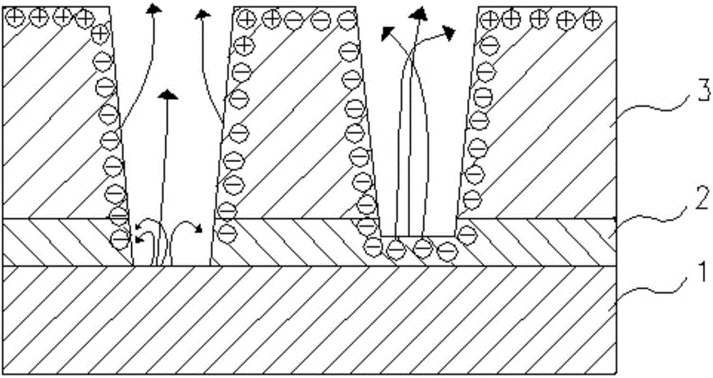
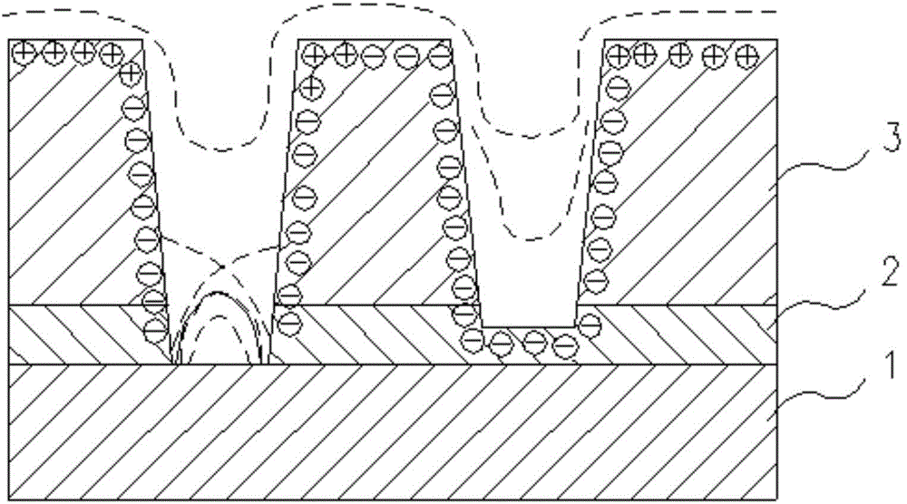
[0008] In order to achieve the above object, the present invention provides a detection method for product through-hole etching defects, which first establishes a through-hole conductive layer test module of the product to be tested, and deposits interconnected and The metal line designed with reference to the pattern structure via hole layout size of the tested product, and, in the hard mask etching process of establishing the test module, each via hole in the product is between each area where each projection of the hard mask layer is located There is photoresist for isolation, and the original trench structure connecting the through holes is improved to a discontinuous trench structure or through hole structure; then the insulating layer is etched and the through holes are filled with copper and planarized; finally, the electronic Inspection by beam defect scanner; this method avoids the effect of Faraday cup when detecting under-etch defects, and also overcomes the problem that not all via defects can be detected after copper planarization, thereby improving via defect detection The success rate can provide data reference for the optimization of the process window, and provide guarantee for the improvement of semiconductor online manufacturing and yield rate

Method used


Image

  • Product through hole etching defect detection method
  • Product through hole etching defect detection method
  • Product through hole etching defect detection method

Examples


Embodiment Construction

[0037] Attached below Figure 5-13 , the specific embodiment of the present invention will be further described in detail.

[0038] It should be noted that, in the following embodiments, a 55nm logic product is taken as an example for illustration, and the etching success rate of the through hole of the connection layer between the semiconductor device layer and the first metal layer of the product is tested. test module.

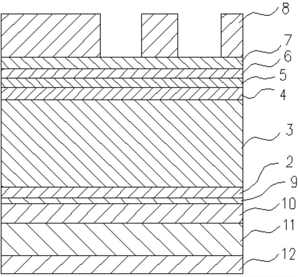
[0039] see Figure 5 , Figure 5 It is a flow diagram of a detection method for product through hole etching defects in the present invention; it illustrates a detection method for product through hole etching defects, the product includes a semiconductor device layer and the semiconductor device layer during etching A metal silicide layer 9, a barrier layer 2, an insulating layer 3, an oxide film layer 4, a hard mask layer 5, a silicon oxide layer 6, an antireflection layer 7 and a photoresist layer 8 are sequentially formed; the semiconductor device la...


PUM


Abstract

The invention discloses a product through hole etching defect detection method. The method comprises the steps that a through hole conducting layer testing module for a product to be detected is built at first, and mutually-communicated metal wires which are designed by referring to the graph structure through hole layout and size of the product to be detected are deposited on the testing module; in the hard mask etching technology where the testing module is built, areas where projections, formed by through holes in the product, on a hard mask layer are located are isolated by photoresist, and original groove structures for connecting the through holes is improved to be discontinuous groove structures or through hole structures; then insulating layer through hole etching is carried out, and the through holes are filled with copper which is flattened; finally, an electron beam defect scanner is adopted for detection. According to the product through hole etching defect detection method, the Faraday cup influences produced in the etching defect detection process can be avoided, and the problem that defects of all the through holes cannot be detected after the copper is flattened is solved, so that the through hole defect detection success rate is improved, data references are provided for technological window optimization, and guarantees are provided for semiconductor on-line manufacturing and yield improvement.

Description

technical field [0001] The invention relates to the technical field of integrated circuit manufacturing, in particular to a detection method for through-hole etching defects of semiconductor integrated circuit products. Background technique [0002] With the development of integrated circuit technology and the proportional reduction of critical dimensions, insufficient etching of copper connection via holes and defects of missing via holes in the back-end process of semiconductor devices have increasingly become one of the bottlenecks in the development of integrated circuits, such as etching first The etching process of the hard mask and then etching the through hole, the through hole etching is often affected by the cleaning process after the hard mask layer is etched, the through hole body and the photolithography process of the through hole etching, resulting in the through hole Under-etching defects and the detection of under-etching defects in back-end through-holes ar...

Claims


Application Information

Patent Timeline
Patent Type & Authority Applications(China)
IPC IPC(8): H01L21/66
CPCH01L22/12
Inventor 范荣伟陈宏璘龙吟顾晓芳
Owner SHANGHAI HUALI MICROELECTRONICS CORP
Learn More