Method and apparatus for manufacturing semiconductor device

A manufacturing method and semiconductor technology, which are applied in the field of semiconductor device manufacturing and semiconductor device manufacturing equipment, can solve problems such as poor conduction, and achieve the effect of high yield

Inactive Publication Date: 2014-11-12
TORAY IND INC
View PDF11 Cites 21 Cited by
  • Summary
  • Abstract
  • Description
  • Claims
  • Application Information

AI Technical Summary

Problems solved by technology

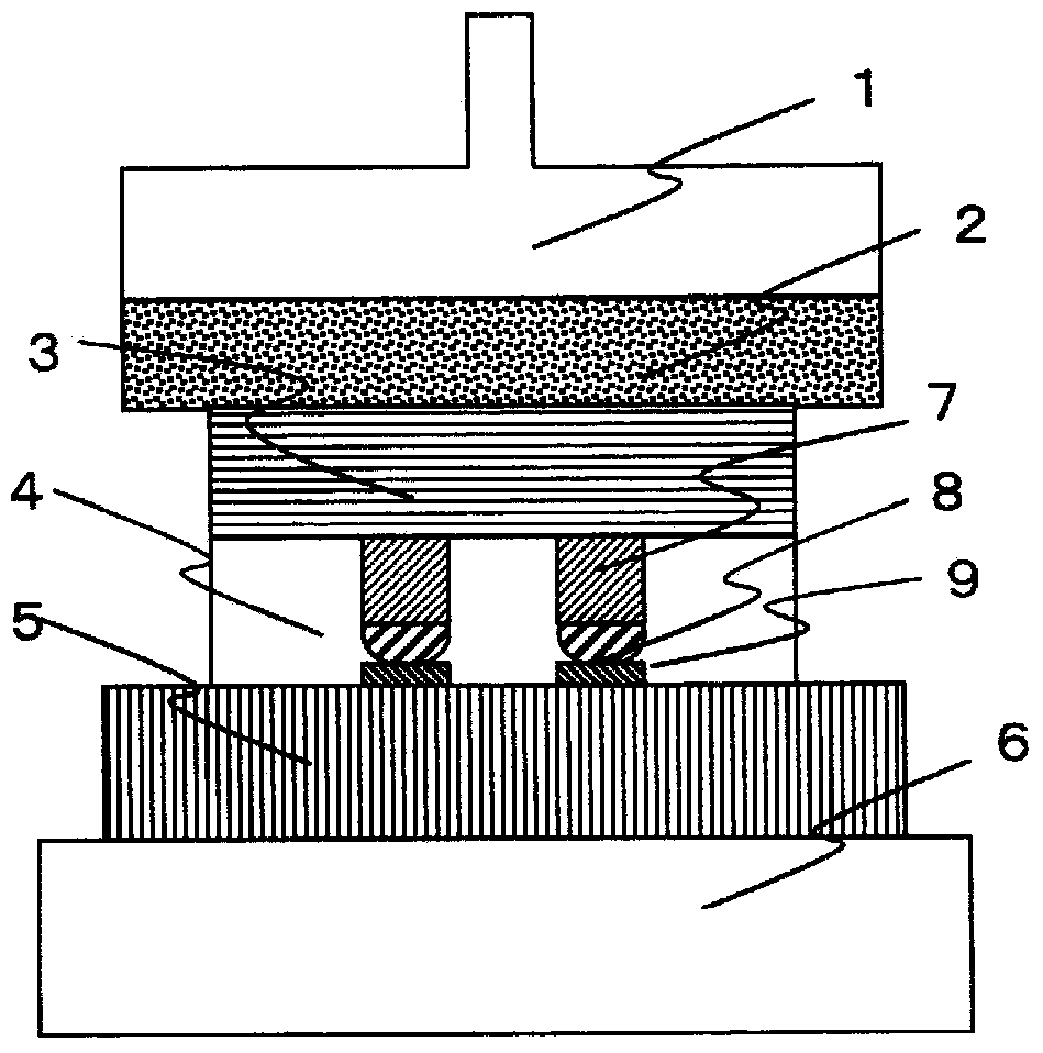
[0013] However, when these protective films are used to perform solder connection through the adhesive film, there is a problem that the resin of the adhesive film is sandwiched between the bump and the electrode pad, resulting in poor conduction, etc.

Method used


Image

  • Method and apparatus for manufacturing semiconductor device
  • Method and apparatus for manufacturing semiconductor device
  • Method and apparatus for manufacturing semiconductor device

Examples


Embodiment 1~ Embodiment 3

[0132] Aluminum foils having a thickness of 6 μm, 12 μm, and 20 μm were used as the protective film, and thermosetting adhesive film 2 was used as the thermosetting adhesive film, and the encapsulation properties were evaluated by the method described above. In Examples 1 to 3, the exposed thermosetting adhesive film did not stick to the pick-up tool, and both the conduction evaluation and the cross-sectional observation evaluation were A. The results are shown in Table 1.

Embodiment 4~ Embodiment 6

[0134] As a thermosetting adhesive film, except having used the thermosetting adhesive film 1, it evaluated similarly to Example 1 - Example 3, respectively. Both conduction evaluation and cross-sectional observation evaluation were A. The results are shown in Table 1.

Embodiment 7~ Embodiment 10

[0136] As a protective film, it evaluated similarly to Example 1 except having used the copper foil of thickness 3 micrometers, 5 micrometers, 18 micrometers, and 30 micrometers, respectively. In the case of using a copper foil with a film thickness of 30 μm (Example 10), when a cross-sectional observation of one sample was carried out, there was 10% or more intrusion, but for others, there was no exposed thermosetting adhesive film. In the case of the pick-up tool, the conduction evaluation and cross-sectional observation evaluation were all A. The results are shown in Table 1.


PUM


Abstract

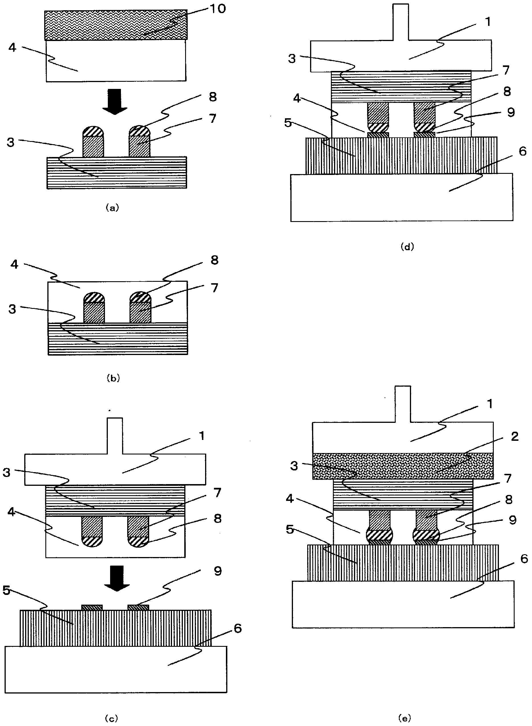
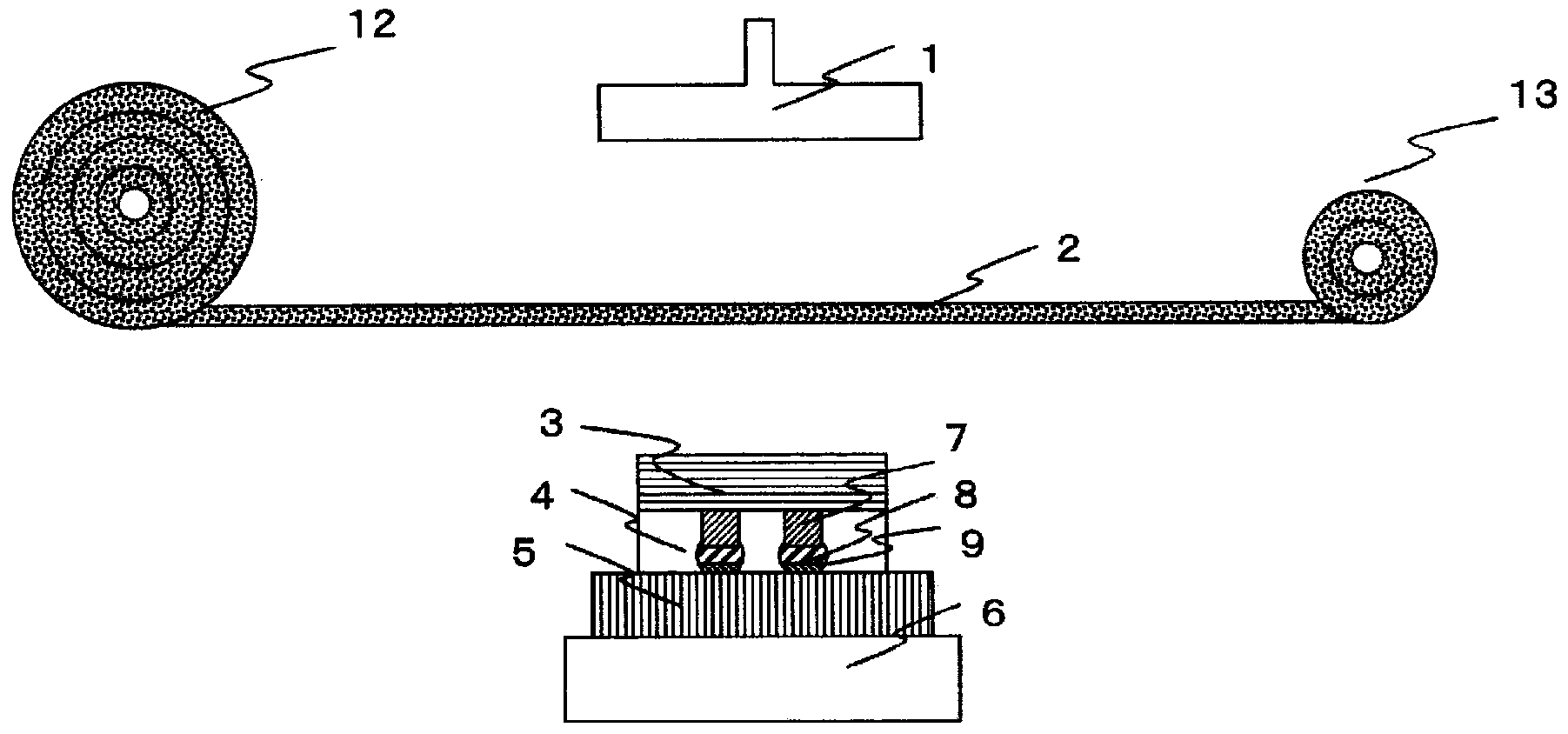
Provided is a method for manufacturing a semiconductor device that solders to connect a semiconductor chip having bumps via a heat-hardened bonding agent layer to a substrate having an electrode corresponding to the bumps that includes, in succession, (A) a process for forming the heat-hardened bonding layer in advance on a surface having the bumps of a semiconductor chip; (B) a process that matches the surface on the heat-hardened bonding agent layer side of the semiconductor chip formed with a heat-hardened bonding agent layer to a substrate, and pre-bonds by using a heat seal to obtain a pre-bonded layer; and (C) places a protective film having thermal conductivity of at least 100 W / mK between the heat seal and the surface on the semiconductor chip side of the pre-bonded layer and uses a heat seal to harden the heat-hardened bonding agent layer simultaneously to melting the solder between the semiconductor chip and the substrate. A method for manufacturing a semiconductor device is that obtains good connections without sandwiching resin between the solder bumps and an electrode pad is provided.

Description

technical field [0001] The present invention relates to a method and device for manufacturing semiconductor devices used in personal computers and mobile terminals. More specifically, the present invention relates to a circuit board formed by soldering semiconductor chips such as ICs and LSIs to circuit boards such as flexible substrates, glass fiber epoxy substrates, glass substrates, ceramic substrates, silicon interposers, and silicon substrates. A method and apparatus for manufacturing a semiconductor device, such as a semiconductor device, or a semiconductor chip laminate in which semiconductor chips are bonded together by soldering. Background technique [0002] In recent years, as semiconductor devices have been miniaturized and densified, as methods for packaging semiconductor chips on circuit boards, flip-chip packaging and three-dimensional stack packaging in which semiconductor chips are three-dimensionally stacked through through electrodes penetrating the chips ...

Claims


Application Information

Patent Timeline
Patent Type & Authority Applications(China)
IPC IPC(8): H01L21/60H01L25/065H01L25/07H01L25/18
CPCH01L2224/14181H01L24/29H01L2223/54426H01L2224/81132H01L2224/8113H01L2224/27334H01L2224/27003H01L2924/15788H01L2224/29386H01L24/16H01L2224/73104H01L2224/16146H01L24/73H01L2224/2732H01L24/13H01L2225/06565H01L2224/13147H01L2224/27416H01L2224/131H01L2224/83191H01L24/75H01L2924/15787H01L25/50H01L2224/83862H01L2224/13111H01L2224/75252H01L24/83H01L2224/2929H01L2224/0557H01L2224/9211H01L2224/27436H01L2224/32225H01L25/0657H01L24/92H01L2224/7532H01L2224/81191H01L2924/00013H01L2224/81815H01L2224/94H01L2224/83203H01L2924/10253H01L2224/32145H01L2224/73204H01L2225/06517H01L2224/81005H01L2224/13082H01L2224/81203H01L2225/06541H01L2224/13025H01L2225/06513H01L24/27H01L24/32H01L2924/157H01L2224/16238H01L2224/75317H01L24/81H01L2224/0401H01L2924/00014H01L2924/1301H01L2224/16225H01L2924/00012H01L2224/27H01L2924/01047H01L2224/16145H01L2924/00H01L2224/81H01L2224/83H01L2224/13099H01L2224/05099H01L2224/05599H01L2924/014H01L2224/05552H01L2224/75315H01L2224/75314B32B37/0046B32B38/004B32B2307/202B32B2311/00B32B2457/14H01L2224/75253H01L2224/753
Inventor 朝日升野中敏央新关彰一
Owner TORAY IND INC
Why Eureka
Try Eureka