
Cleaning and flaw detection robot for electric power metal parts

A technology of electric metals and robots, applied in the field of robots, can solve the problems of limited robot degrees of freedom, single function of robots, non-destructive flaw detection, etc., and achieve the effects of easy wiring and installation, strong climbing ability, and strong flexibility

Active Publication Date: 2014-11-19
ELECTRIC POWER RES INST OF GUANGDONG POWER GRID +1
View PDF6 Cites 26 Cited by
  • Summary
  • Abstract
  • Description
  • Claims
  • Application Information

AI Technical Summary

Problems solved by technology

[0005] Although the above-mentioned robots all have certain functions of walking, climbing and flaw detection, because the robots are limited by their own mechanical mechanisms (most of them adopt wheel type, crawler type, etc.), the freedom of robot movement in space is greatly restricted. , it is often impossible to perform free climbing and non-destructive flaw detection in the space when testing complex metal parts in the power system, especially for flaw detection of small-diameter pipelines, discontinuous or interlaced power metal parts, etc. The defect is particularly obvious
In addition, the functions of existing robots are relatively single, for example, in an environment with a lot of dust or obstacles, they cannot be effectively cleaned and operated, and the detection methods have low precision
Moreover, due to the complexity of the robot's own mechanism, it leads to the complexity of the system structure and control, which increases the difficulty of the robot's balance and crawling, so that it cannot effectively perform motion planning for the working environment to complete effective detection.

Method used


Image

  • Cleaning and flaw detection robot for electric power metal parts
  • Cleaning and flaw detection robot for electric power metal parts
  • Cleaning and flaw detection robot for electric power metal parts

Examples


Embodiment Construction

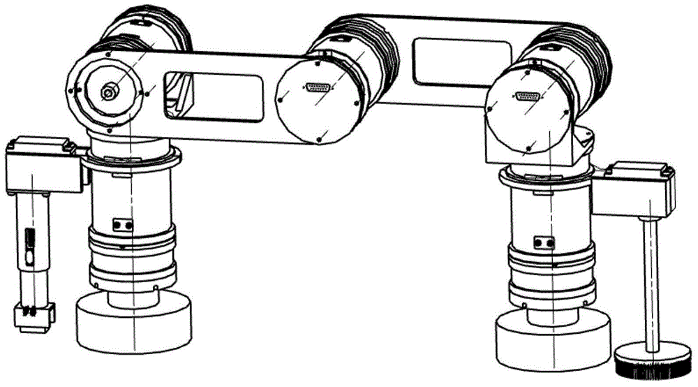
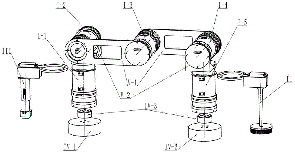
[0040] Such as figure 1 , 2 As shown, it is a cleaning and flaw detection robot for electric metal parts of the present invention, including a robot body, a cleaning device II, a flaw detection device III and a control system. The robot body includes at least three cylindrical longitudinal rotary joints arranged in parallel and arranged longitudinally, Two cylindrical walking rotary joints I-1, I-5 perpendicular to the longitudinal rotary joints, a pair of electromagnetic suckers VI-1, VI-2 and at least four connecting plates, through which the vertical rotary joints pass At least two connecting plates are fixedly connected to form a rotatable connection. The upper end of the walking revolving joint is fixedly connected to the longitudinal revolving joints located on both sides through the other two connecting plates to form a rotatable connection so that each revolving joint is connected in series. The walking revolving joint I- 1. I-5 can rotate along the vertical plane, el...


PUM


Abstract

The invention discloses a cleaning and flaw detection robot for electric power metal parts. All longitudinal rotating joints are in rotatable connection through connecting plates. The upper ends of walking rotating joints are in rotatable connection with the longitudinal rotating joints on the two sides through connecting plates to enable all the rotating joints to be in integrally series connection, and electromagnetic chucks are fixed at the lower ends of the walking rotating joints. A main control unit sends instructions to control units placed in all rotating joints to control all the rotating joints to move to achieve stretching and shrinkage of a robot body, and meanwhile the positions of the electromagnetic chucks are adjusted. The main control unit sends instructions to control units on a cleaning device and a flaw detection device to control the cleaning device and the flaw detection device to work. According to the cleaning and flow detection robot for the electric power metal parts, the electromagnetic chucks are used for sucking and positioning, various climbing step states under different operation environments can be achieved, the electric power metal parts can be cleaned and detected, and the cleaning and flaw detection robot is particularly suitable for flow detection of small-diameter pipelines, discontinuous or staggered-connection electric power metal parts and the like.

Description

technical field [0001] The invention relates to a robot, in particular to a cleaning and flaw detection robot for electric metal components. Background technique [0002] Today, criss-crossing pipelines are laid all over the world. The daily tap water, heating system, power supply system, oil in the chemical industry, and natural gas transmission are all inseparable from the medium of pipelines. While pipelines bring convenience to human production and life, they also bring new problems. Due to environmental corrosion, material aging, operating conditions and other reasons, many pipelines have problems such as difficult cleaning, pipeline cracks, pits and other defects that make it difficult to monitor, which puts higher requirements on pipeline maintenance, monitoring and dust removal. In the power system, thermal power generation is mainly used in my country, and thermal power plants need to be regularly shut down for inspection during the operation process after infrastr...

Claims


Application Information

Patent Timeline
IPC IPC(8): B25J9/00B25J19/00G01N29/04
Inventor 钟万里游凡王伟钟力强梁永纯李文胜谢涛肖晓晖
Owner ELECTRIC POWER RES INST OF GUANGDONG POWER GRID
Learn More