Efficient hydraulic rock drill

A hydraulic rock drill and high-efficiency technology, applied in mechanical equipment, reciprocating drilling rigs, drilling equipment, etc., can solve the problems affecting the moving thrust of the valve core, reducing the frequency of valve core action, and reducing the frequency of piston impact, so as to improve the rock drilling effect, The effect of reducing consumption and solving wear problems

Inactive Publication Date: 2014-11-19
李田生
View PDF12 Cites 6 Cited by
  • Summary
  • Abstract
  • Description
  • Claims
  • Application Information

AI Technical Summary

Problems solved by technology

Due to the different section of the spool in this structure of the rock drill, when there is oil return pressure or the oil return pressure is high, the moving thrust of the spool will b

Method used


Image

  • Efficient hydraulic rock drill
  • Efficient hydraulic rock drill
  • Efficient hydraulic rock drill

Examples


Embodiment 1

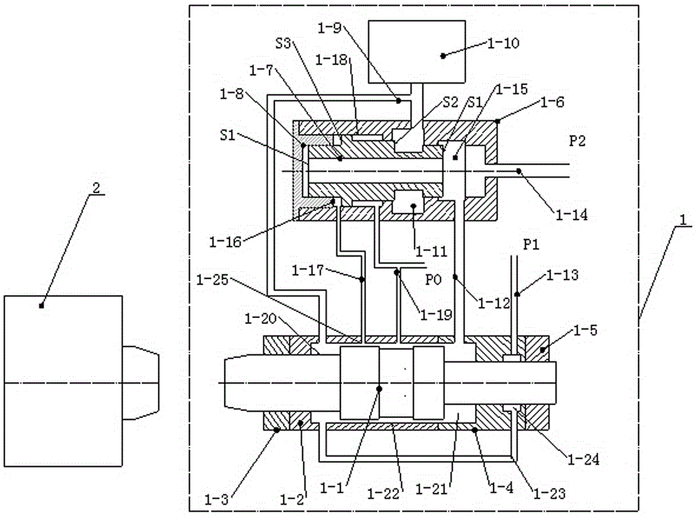
[0020] A high-efficiency hydraulic rock drill of the present invention is composed of two parts: a piston impactor 1 and a shank rotator 2, wherein:

[0021] refer to figure 1 , Piston impactor 1 consists of piston 1-1, front cylinder liner 1-2, front sealing device 1-3, rear cylinder liner 1-4, rear sealing device 1-5, valve body 1-6, valve core 1-7 , valve cover 1-8, first oil passage 1-9, accumulator 1-10, oil inlet chamber 1-11, second oil passage 1-12, oil inlet 1-13, oil return passage 1- 14. Oil return chamber 1-15, oil control chamber 1-16, third oil passage 1-17, spool oil chamber 1-18, fourth oil passage 1-19, front cylinder oil chamber 1-20, rear cylinder oil Chamber 1-21, oil chamber 1-22, fifth oil passage 1-23, support oil chamber 1-24 and oil control port 1-25 form. P1>P2, P0 is the pressure of the oil return tank. The area of ​​the end surface of the spool 1-7 is S3>S2>S1. The piston 1-1 is installed in the front cylinder liner 1-2 and the rear cylinder lin...

Embodiment 2

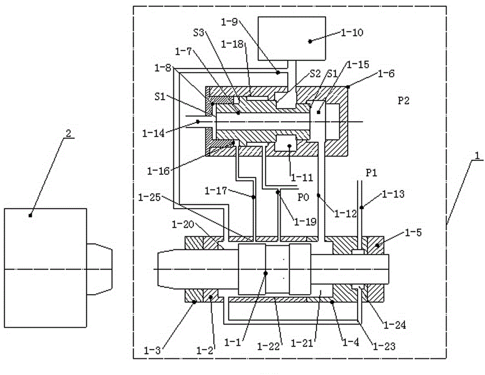
[0025] refer to image 3 , the rear cylinder liner 1-4 oil chamber 1-21 hydraulic oil passes through the oil passage 1-12 from the oil chamber 1-15 through the inner hole of the valve core 1-7, and opens the oil return passage 1-8 from the valve cover 1-8 14 is connected to reversing valve 2-19, and all the other are with embodiment 1.


PUM


Abstract

The invention discloses an efficient hydraulic rock drill. An energy accumulator is arranged upon a valve body in a piston impacter and communicated with an oil inlet chamber of the valve body and an oil chamber of a front cylinder sleeve respectively through a first oil channel. The oil chamber of the front cylinder sleeve is communicated with a support oil chamber of a back cylinder sleeve through a fifth oil channel. The support oil chamber is communicated with an oil inlet. An oil controlling chamber of a valve core is communicated with an oil controlling opening of the front cylinder sleeve through a third oil channel. An oil returning chamber of the valve body is communicated with an oil chamber of the back cylinder sleeve through a second oil channel and communicated with an oil returning channel which is connected with a reversing valve of a rotary portion. The other oil controlling opening of the front cylinder sleeve is communicated with a valve core oil chamber through a forth channel which enters an oil tank. A hydraulic motor and the reversing valve are arranged in a shank rotator. One end of the reversing valve is communicated with the oil returning channel of the piston impacter, and the other end of the reversing valve is communicated with the hydraulic motor. According to the arrangement, the abrasion problem of an impacting piston and a support is solved to decrease abrasion of the piston; energy consumption of an impacting portion is converted into power of the rotary portion, so that energy consumption is greatly reduced, and working efficiency is improved.

Description

technical field [0001] The invention relates to engineering machinery, in particular to a high-efficiency hydraulic rock drill. Background technique [0002] The working principle of the current hydraulic rock drill is to use the pressure difference effect to force the impact piston to perform high-speed reciprocating motion in the oil cylinder to impact the drill rod to break the rock. Due to the high-speed impact movement of the piston under high pressure, the requirements for the sealing structure of the cylinder body and the structure of the front and rear guide sleeves supporting the movement of the piston are very high, and the requirements for the material treatment and machining accuracy of the impact piston, shank tail, and guide sleeve are also very high. Therefore, the manufacturing cost of the current hydraulic rock drill is high, and the maintenance cost is high. [0003] For this reason, the applicant of this case has once disclosed a kind of hydraulic rock dr...

Claims


Application Information

Patent Timeline
IPC IPC(8): F15B1/02E21B1/26
Inventor 李田生
Owner 李田生
Why Eureka
Try Eureka