Wet clutch

A wet clutch and clutch technology, applied in the field of clutches, can solve the problems of long clutch disengagement time, unstable clutch combination, easy damage to the sealing ring, etc., so as to simplify the design and processing technology, simplify the installation and assembly technology, and improve the sealing area. Effect

Active Publication Date: 2014-11-19
LUOYANG REASTAR TRANSMISSION
View PDF5 Cites 1 Cited by
  • Summary
  • Abstract
  • Description
  • Claims
  • Application Information

AI Technical Summary

Problems solved by technology

[0002] In the prior art, in the wet clutches used in power shift gearboxes and automatic gearboxes, O-rings or metal seal rings are usually used to seal the clutch pistons, and the seal rings are easily damaged, resulti

Method used


Image

  • Wet clutch
  • Wet clutch
  • Wet clutch

Examples


Example Embodiment

[0021] The present invention will be described in further detail below in conjunction with the accompanying drawings and specific embodiments.

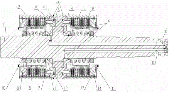
[0022] As shown in the figure, a wet clutch includes a main shaft 1, a clutch piston cylinder 3, a clutch outer hub 2 and a clutch inner hub 15. The clutch piston cylinder 3 is fixedly connected to the main shaft 1. In order to ensure the reliability of the connection, increase the To transmit torque, simplify the design and processing technology, reduce the production cost and simplify the installation and assembly process, this embodiment adopts taper interference fit connection, and the taper can be any one of 1:10~1:50.

[0023] The clutch outer hub 2 is fixedly connected to the clutch piston cylinder 3. In this embodiment, the clutch outer hub 2 and the clutch piston cylinder 3 are fixedly connected by laser welding. The laser welding method can minimize the deformation of the clutch hub, and improve production efficiency and pr...


PUM

PropertyMeasurementUnit
Diameteraaaaaaaaaa

Abstract

A wet clutch comprises a spindle, a clutch piston cylinder, a clutch outer hub and a clutch inner hub. The clutch piston cylinder is connected with the spindle. The clutch outer hub is connected with the clutch piston cylinder. The clutch inner hub is disposed inside the clutch outer hub. Friction plates are disposed on the clutch outer hub. Coupling plates are disposed on the clutch inner hub. A clutch piston is disposed in the clutch piston cylinder. An oilway communicated with the clutch piston cylinder is formed in the spindle. A spring is fixed at one end, away from the bottom of the clutch piston cylinder, of the clutch piston. The other end of the spring is fixedly connected with the spindle. A small hole is formed in the bottom of the clutch piston cylinder and in the bottom of the clutch piston. A butterfly steel plate is fixed at one end, close to the clutch piston, of the clutch inner hub. The wet clutch has the advantages that internal oil pressure change of the clutch can be buffered, transmission stability of the clutch is increased, oil temperature of the clutch can be lowered, gear shifting impact is reduced, and the service life of the clutch is prolonged.

Description

technical field [0001] The invention relates to a clutch, in particular to a wet clutch for an automatic transmission. Background technique [0002] In the prior art, in wet clutches used in power shift transmissions and automatic transmissions, the seal of the clutch piston is usually sealed by an O-ring or a metal sealing ring, and the sealing ring is easily damaged, resulting in oil leakage from the clutch. In addition, the inside of the clutch piston cavity is usually closed, resulting in unstable clutch engagement, long clutch disengagement time, and high temperature conditions. Contents of the invention [0003] In order to solve the above-mentioned technical problems, the present invention provides a wet clutch, which engages smoothly and disengages quickly, avoids high temperature during use, and prolongs the service life of the clutch. [0004] The technical scheme adopted by the present invention in order to solve the above technical problems is: a wet clutch, ...

Claims


Application Information

Patent Timeline
IPC IPC(8): F16D25/063F16D25/12
Inventor 施贵滨李辉李虎何芳陆红兵
Owner LUOYANG REASTAR TRANSMISSION
Why Eureka
Try Eureka