Liquid removing device used outside water cooling type vertical condenser pipes

A condensing tube and water-cooled technology, which is applied in the field of liquid removal device, can solve the problems such as the decrease of the heat transfer effect of the condensing tube, the reduction of the condensation thermal resistance, and the weakening of the condensation efficiency, so as to improve the continuous working time, enhance the disturbance, and increase the heat transfer and the effect of condensation efficiency

Active Publication Date: 2014-11-19
东南大学常州研究院
View PDF7 Cites 3 Cited by
  • Summary
  • Abstract
  • Description
  • Claims
  • Application Information

AI Technical Summary

Problems solved by technology

[0006] In order to overcome the deficiencies of existing water-cooled vertical condensing tube outer condensate film weakening condensation efficiency, condensation tube inner wall deposition or adsorption of impurities caused by condensation tube heat transfer effect decline, the present invention a new type of water-cooled vertical condensing tube outer scraping liquid The device uses an automatic reciprocating liquid scraping device to scrape off the liquid film and droplets on the outer wall of the condenser tube, so that the condensation thermal resistance outside the condenser tube is reduced, thereby improving the condensation efficiency

Method used


Image

  • Liquid removing device used outside water cooling type vertical condenser pipes
  • Liquid removing device used outside water cooling type vertical condenser pipes
  • Liquid removing device used outside water cooling type vertical condenser pipes

Examples


Embodiment Construction

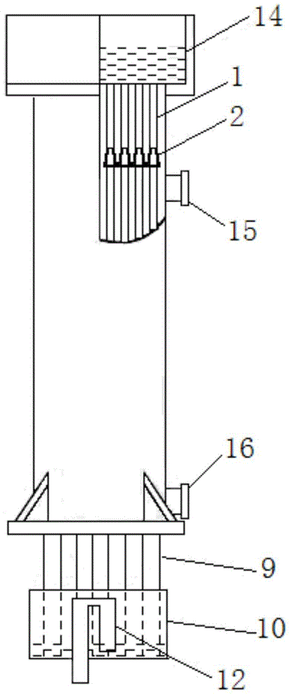
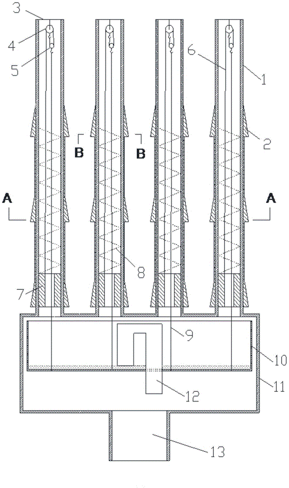
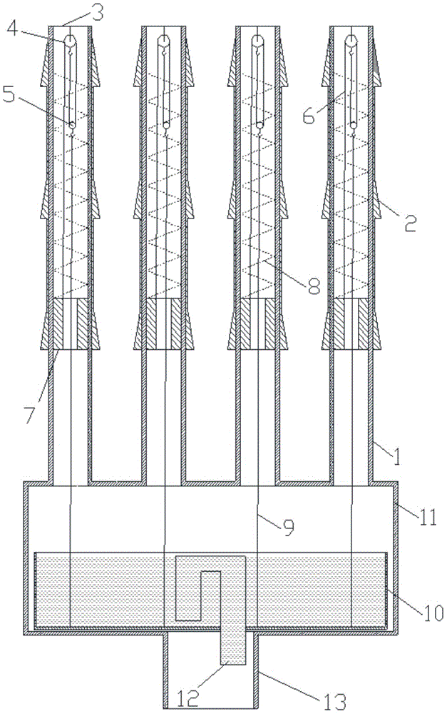
[0035] like Figure 1-Figure 5 As shown, the water-cooled vertical condenser tube external scraping device of the present invention consists of a condenser tube 1, a scraping device 2, a support frame 3, a fixed pulley 4, a movable pulley 5, a pulley line 6, a suspension ring magnet 7, a spring 8. Suspension line 9, suspension basin 10, thick pipeline 11, siphon 12, cooling water outlet 13. Cooling water enters in the condensation pipe 1 by the top water tank 14, and flows out from the bottom of the condensation pipe 1, flows into the suspended water receiving basin, and flows out from the siphon pipe 12 when reaching a certain liquid level in the water receiving basin. Refrigerant vapor enters the condenser from the condensed gas inlet 15 on the top of the wall, and flows out from the condensed liquid outlet 16 after being condensed into liquid on the outer wall of the condensing pipe 1 . The inside of the condensation pipe 1 is cooling water, and the space outside the pipe ...


PUM


Abstract

The invention discloses a liquid removing device used outside water cooling type vertical condenser pipes. The liquid removing device is composed of the condenser pipes, liquid scraping devices, supporting frames, fixed pulleys, moving pulleys, pulley lines, suspension annular magnets, springs, suspension lines, a suspension water collecting basin, a thick pipeline, a siphon and a cooling water outlet. The outer wall faces of the annular magnets are in sliding contact with the inner wall faces of the condenser pipes, the lower ends of the springs are fixedly connected with the upper ends of the annular magnets, and the outer rings of the springs are slightly attached to the inner wall faces of the condenser pipes and are in sliding contact with the inner wall faces of the condenser pipes. The liquid scraping devices are located outside the condenser pipes, the inner wall faces of the liquid scraping devices are in sliding contact with the outer wall faces of the condenser pipes, the suspension water collecting basin is located below the condenser pipes and fixedly connected with hooks arranged at the lower portions of the moving pulleys through the suspension lines, and the siphon is located in the water collecting basin and fixedly connected with the bottom of the water collecting basin. Liquid film and liquid drops on the outer wall faces of the condenser pipes are scraped off through the liquid scraping devices automatically conducting reciprocating movement, and condensation thermal resistance outside the condenser pipes is reduced, so that condensing efficiency is improved.

Description

technical field [0001] The invention relates to a novel liquid removal device for water-cooled vertical condensing tubes, which is a device for enhancing heat transfer and phase change in a condenser. Background technique [0002] A condenser is a device that converts a gas or vapor into a liquid. Condensers are very important equipment in refrigeration, air-conditioning and chemical industries. Power plants use many condensers to condense the steam discharged from turbines; in refrigeration plants, condensers are used to condense refrigeration vapors such as ammonia and Freon. Condensers are used in the petrochemical industry to condense hydrocarbons and other chemical vapors. During distillation, the device that converts vapor into liquid is called a condenser. All condensers operate by removing heat from a gas or vapor. [0003] Condensers can be divided into three categories: water-cooled, air-cooled, and evaporative according to their cooling media. Due to the large...

Claims


Application Information

Patent Timeline
Patent Type & Authority Applications(China)
IPC IPC(8): F28B9/08
Inventor 杨柳张小松杜垲
Owner 东南大学常州研究院
Why Eureka
Try Eureka