Optical machine positioning survey method of intersection survey system

A technology of intersection measurement and positioning measurement, which is used in measurement devices, measurement angles, surveying and navigation, etc. It can solve the problems of inability to measure directly, the size of intersection measurement cameras and mirrors are small, and achieve low hardware configuration requirements and high positioning accuracy. , the effect of the simple method

Active Publication Date: 2014-11-19
BEIJING INST OF CONTROL ENG
View PDF5 Cites 10 Cited by
  • Summary
  • Abstract
  • Description
  • Claims
  • Application Information

AI Technical Summary

Problems solved by technology

[0003] Intersection measurement cameras and mirrors are small in size, placed at an angle and located inside the product, which cannot be directly measured by traditional measurement methods

Method used


Image

  • Optical machine positioning survey method of intersection survey system
  • Optical machine positioning survey method of intersection survey system

Examples


Embodiment Construction

[0020] The present invention will be further introduced below in conjunction with the accompanying drawings.

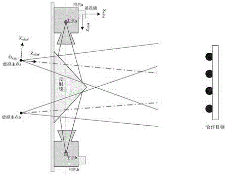
[0021] After the mirror assembly is completed, the pointing accuracy of its normal in the reference mirror coordinate system directly affects the mirror image result from the target marker coordinate system to the target marker mirror coordinate system, which in turn affects the measurement accuracy of the interactive measurement subsystem.

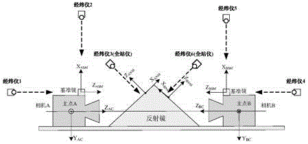
[0022] The intersection measuring system of the present invention comprises camera A, camera B and reflecting mirror; Camera A, camera B are symmetrically placed on both sides of reflecting mirror; Reference mirror A and reference mirror B are respectively installed on camera A and B; Reflecting mirror has two Symmetrical reflective surfaces.

[0023] The optical-mechanical positioning measurement method of the intersection measurement system of the present invention comprises the following steps:

[0024] The first step is to e...


PUM


Abstract

The invention discloses an optical machine positioning survey method of an intersection survey system. The optical machine positioning survey method comprises the steps: respectively establishing a reference mirror A coordinate system O(ASM)X(ASM)Y(ASM)Z(ASM), a reference mirror B coordinate system O(BSM)X(BSM)Y(BSM)Z(BSM), a first reflector mirror virtual coordinate system O(ANM)X(ANM)Y(ANM)Z(ANM) and a second reflector mirror virtual coordinate system O(BNM)X(BNM)Y(BNM)Z(BNM) by adopting six theodolites respectively, resolving a rotation matrix CA of the coordinate system O(ANM)X(ANM)Y(ANM)Z(ANM) to the coordinate system O(ASM)X(ASM)Y(ASM)Z(ASM), resolving a rotation matrix CB of the coordinate system O(BNM)X(BNM)Y(BNM)Z(BNM) to the coordinate system O(BSM)X(BSM)Y(BSM)Z(BSM); resolving vectors RA and RB according to the rotation matrixes CA and CB; obtaining a rotation matrix C1 between a virtual coordinate system of a camera A and the reference mirror A coordinate system according to the RA; obtaining a rotation matrix C2 between a virtual coordinate system of a camera B and the reference mirror B coordinate system according to the RB and a mirror image equation; completing relative relationship testing of the reference mirror A coordinate system and the reference mirror B coordinate system to obtain a rotation matrix C3; and determining a rotation matrix C4 between the virtual coordinate systems of the two cameras according to the C1, the C2 and the C3. The optical machine positioning survey method is simple to operate, high in precision, and capable of reducing the configuration requirement on hardware.

Description

technical field [0001] The invention relates to an optical-mechanical positioning measurement method for an intersection measurement system. Background technique [0002] Such as figure 1 As shown, the intersection measurement system is composed of the intersection measurement cameras A and B installed on the tracking aircraft and the cooperative target installed on the target aircraft. The intersection measurement system is equipped with a flat mirror. Enter the measurement camera to form a measurement image. According to the principle of visual measurement, the relative position and relative velocity, relative attitude angle and relative attitude angular velocity of the camera coordinate system relative to the target marker coordinate system can be calculated, so as to provide relative navigation measurement information for GNCC. [0003] Intersection measurement cameras and mirrors are small in size, placed at an angle, and located inside the product, which cannot be dir...

Claims


Application Information

Patent Timeline
Patent Type & Authority Applications(China)
IPC IPC(8): G01C25/00G01C11/02G01C1/00
CPCG01C25/00
Inventor 赵春晖郭绍刚王京海钟俊张丽华王晓燕
Owner BEIJING INST OF CONTROL ENG
Why Eureka
Try Eureka