Transmission and friction experiment table for multifunctional mechanical part

A technology of mechanical parts and test benches, which is applied in the testing of machine gears/transmission mechanisms and testing of wear resistance, etc. It can solve problems such as few detection parameters, narrow measurement range, and influence on transmission accuracy, and achieve highly unified boundary conditions and measurement The effect of large range and multiple detection parameters

Inactive Publication Date: 2014-11-19
CHONGQING UNIV
View PDF7 Cites 34 Cited by
  • Summary
  • Abstract
  • Description
  • Claims
  • Application Information

AI Technical Summary

Problems solved by technology

[0003] Existing test benches for rotary transmission mechanisms are generally designed specifically for performance testing of certain parameters of a certain mechanism. The type of test object is often relatively single, with fewer detection parameters and a relatively narrow measurement range.
For example, CN102261992A discloses a spiral bevel gear coupling transmission test bench structure with variable stiffness elastic support, which can only carry out spiral bevel gear coupling transmission experiments, and an overly long driving shaft will affect the transmission accuracy
For example, the rolling friction and wear tester disclosed in CN102419291A can only carry out rolling friction test, and the testing machine cannot guarantee the parallelism of the two main shafts during the loading process of force.

Method used


Image

  • Transmission and friction experiment table for multifunctional mechanical part
  • Transmission and friction experiment table for multifunctional mechanical part
  • Transmission and friction experiment table for multifunctional mechanical part

Examples


Embodiment 1

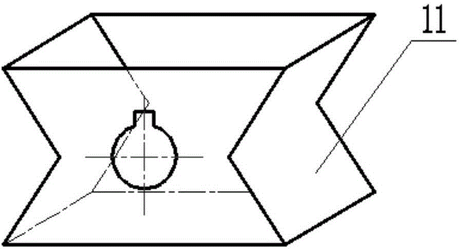
[0042] This embodiment is to adopt the experiment platform of the present invention to carry out multi-purpose clamping block and ring multi-line or single-line contact friction experiment, such as Figure 4 with Figure 5 . At this time, the multi-purpose clamping block is installed on the output end of the first headstock 10, and the ring is installed on the output end of the second headstock 14, and the first main shaft is rotated to Figure 4 The position shown is locked, adjust the center distance between the two test pieces to the contact state, start the main switch of the test bench, start the first drive motor 2 and the second drive motor 18, open the lubrication system and cooling system, and perform multi-purpose clamping block and Ring multi-line contact friction experiment; use the same multi-purpose clamping block, only need to rotate the first spindle 90° to Figure 5 The position shown is locked, and the center distance between the two test pieces is readjust...

Embodiment 2

[0044] The present embodiment is to adopt the experimental platform of the present invention to carry out the rolling bearing friction experiment, such as Image 6 . At this time, the multi-purpose clamping block is installed on the output end of the first headstock 10, the rolling bearing is installed on the output end of the second headstock 14, and the first main shaft is rotated to Image 6 The position shown is locked, and the rest of the operation process can refer to embodiment 1.

Embodiment 3

[0046] This embodiment is to use the experimental platform of the present invention to carry out the parallel axis gear meshing transmission experiment, such as Figure 7 with Figure 8 . Figure 7 For spur gear meshing transmission experiment, Figure 8 It is a helical gear mesh transmission experiment. At this time, two spur gears or helical gears are respectively installed on the output ends of the first headstock 10 and the second headstock 14 , and the rest of the operation process can refer to Embodiment 1.


PUM


Abstract

The invention relates to a transmission and friction experiment table for a multifunctional mechanical part. The transmission and friction experiment table comprises a first guiding rail, a second guiding rail, a first driving motor, a second driving motor, a first supporting plate, a second supporting plate, a first main shaft box, a second main shaft box, a first test-piece, a second test-piece,a first torque sensor, a second torque sensor, a first rigid coupler, a second rigid coupler, a third rigid coupler, a first supporting plate sliding driving motor, an universal coupler, a loading electric cylinder, a bedplate, an acceleration vibration sensor, a temperature sensor, a displacement sensor, a pressure sensor, a lubricating system, a cooling system and a general controlling computer. According to the invention, various low and high friction pairs in a contact zone can be tested online for frictional wear, energy consumption, vibration and material behaviors under the different loads, rotating speeds and lubrication conditions, and transmission parts and systems can be conducted with friction and transmission process experiments; when testing data is gathered, parts and systems to be tested can be analyzed for the following situations such as frictional wear, power consumption, stress and the service behaviors of transmission pairs, so that the behavior features, variation rules and failure mechanisms of research objects in the operating process can be obtained.

Description

technical field [0001] The invention belongs to a friction wear and transmission performance testing device, in particular to a multipurpose mechanical part transmission and friction test bench. Background technique [0002] The rotating transmission pair mechanism refers to the transmission mechanism for the purpose of transmitting torque, such as gears, cylindrical rollers, tapered rollers, special-shaped rollers, rolling friction wheels, belt transmission pairs, and sprocket transmission pairs. In order to improve the performance of the mechanism, it is necessary to use a test bench with a rotating transmission pair mechanism to study the surface morphology, contact form, and shape changes of the material. Tribological research is not limited to rotating pairs. The same experimental platform can have multiple functions. Different experiments can be carried out without changing the position of most of the structure of the machine, which is conducive to the analysis and com...

Claims


Application Information

Patent Timeline
Patent Type & Authority Applications(China)
IPC IPC(8): G01M13/02G01N3/56
Inventor 孟凡明刘忠程志涛王剑王茜
Owner CHONGQING UNIV
Why Eureka
Try Eureka