
Probe Holder for Modular Scanning Probe Microscopes

A scanning probe and microscope technology, applied in the field of scanning probe testing, can solve the problems of lack of precise positioning and clamping structure, affecting the clamping effect of the probe, changing the scanning area of ​​the sample, etc., achieving good clamping effect and improving test accuracy And test efficiency, reduce the effect of production cost

Inactive Publication Date: 2016-08-17
DALIAN UNIV OF TECH
View PDF8 Cites 2 Cited by
  • Summary
  • Abstract
  • Description
  • Claims
  • Application Information

AI Technical Summary

Problems solved by technology

[0004] Existing scanning probe microscopes correspond to different use modes, such as: atomic force microscope mode, scanning tunneling microscope mode, etc., and have different probe holders. It is not easy to make adjustments to the circuit structure and probe clamping method when conducting scientific research experiments. Change; it is suitable for the probe holder of atomic force microscope and other modes, which presses the probe on the metal block through the elastic sheet, without precise positioning and clamping structure, and the laser spot at the end of the probe cantilever moves every time the probe is replaced. position, the laser optical path needs to be readjusted, which complicates the operation, and after changing the probe, the sample scanning area will change in a large range, which is not conducive to repeated observation; when changing the probe, it is necessary to manually lift the unfixed end of the elastic sheet or loosen it. The screws fixing the elastic sheet are inconvenient to operate, and the elastic sheet is manually lifted for a long time, and the force on the end is uneven, which will cause asymmetric deformation of the elastic sheet, affect the clamping effect of the probe, and then affect the test quality

Method used


Image

  • Probe Holder for Modular Scanning Probe Microscopes
  • Probe Holder for Modular Scanning Probe Microscopes
  • Probe Holder for Modular Scanning Probe Microscopes

Examples


Embodiment 1

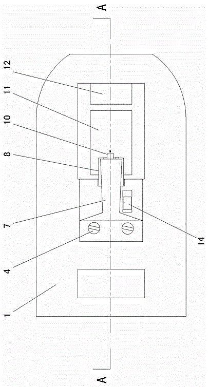
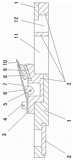
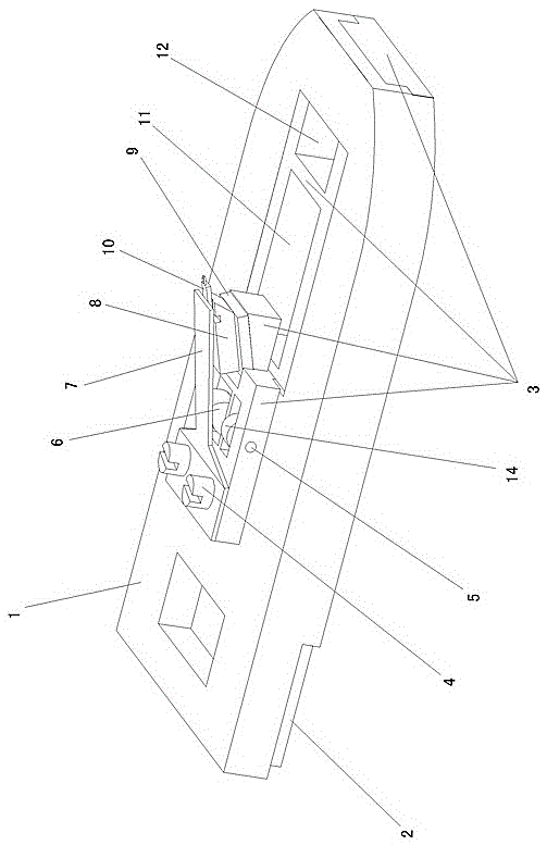
[0018] Such as figure 1 , 2 , shown in 3: 1 support, there is circuit board 2 at one end of support 1, between circuit board 2 and support 1 is the slot-type connection structure, promptly is processed with the slot that coincides with circuit board 2 on support 1, The circuit board 2 can be inserted from the side of the bracket 1 .

[0019] On the bracket 1, there is a clamping frame 3 for installing the probe 10, and the connection between the clamping frame 3 and the bracket 1 is a slot type, that is, the gap between the clamping frame 3 and the bracket 1 is split and the clamping frame 3 is inserted Inside the bracket 1 , the clamping frame 3 and the bracket 1 form a mosaic structure. There is a hollow on the bracket 1, and a signal window 11 for transmitting signals such as laser light and a hand-held frame 12 for easy installation and removal are provided on the clamping frame 3. The signal window 11 and the hand-held frame 12 are just located at the aforementioned hol...

Embodiment 2

[0025] Such as Figure 6 As shown: 1 bracket, there is a circuit board 2 at one end of the bracket 1, and the connection structure between the circuit board 2 and the bracket 1 is a slot type connection structure, that is, a slot matching the circuit board 2 is processed on the bracket 1, and the circuit board 2 Insert it from the side of bracket 1. On the bracket 1, there is a clamping frame 3 for installing the probe 10, and the connection between the clamping frame 3 and the bracket 1 is a slot type, that is, the gap between the clamping frame 3 and the bracket 1 is split and the clamping frame 3 is inserted Inside the bracket 3 , the clamping frame 3 and the bracket 1 form a mosaic structure. A hand-held frame 12 for easy installation and removal is provided on the clamping frame 3 . Probe installation holes 23 are processed on the holder frame 3 . The probe frame for a modular scanning probe microscope of the invention is suitable for a scanning tunneling microscope. ...


PUM


Abstract

The invention discloses a probe rack for a modular scanning probe microscope, which includes a bracket on which a circuit board and a clamping frame for installing probes are arranged. The circuit board and the bracket are connected in a slot type. The clamping frame and the bracket are split, and the clamping frame is inserted into the bracket, and the clamping frame and the bracket form a mosaic structure. The probe holder for the modular scanning probe microscope of the present invention has the advantages of simple operation, good clamping effect, precise probe positioning, improved testing accuracy and testing efficiency, and low manufacturing cost.

Description

technical field [0001] The invention relates to the technical field of scanning probe testing, in particular to a probe frame for a modular scanning probe microscope. Background technique [0002] Scanning probe microscope is a general term for a group of microscopes that use probes to mechanically scan the surface of the sample to obtain sample information, including scanning tunneling microscopes, atomic force microscopes, magnetic force microscopes, friction force microscopes, scanning near-field optical microscopes, static Electric Power Microscope, Magnetic Resonance Force Microscope, Scanning Capacitance Microscope, Scanning Hall Effect Microscope, etc. Among them, scanning tunneling microscope and atomic force microscope are the most commonly used. Scanning tunneling microscope is the first scanning probe microscope invented by IBM's G.Binning and H.Rohrer in 1982. It uses the quantum tunneling effect to obtain the information of the sample surface by detecting the t...

Claims


Application Information

Patent Timeline
Patent Type & Authority Patents(China)
IPC IPC(8): G01Q70/02
Inventor 陈莉李克洪刘军山刘冲
Owner DALIAN UNIV OF TECH
Learn More