Touch screen and display device

A touch screen and touch electrode technology, which is applied in optics, instruments, electrical digital data processing, etc., can solve the problems of poor operability of display devices, and achieve the effect of extending the application range

Active Publication Date: 2014-11-19
CHONGQING BOE OPTOELECTRONICS +1
View PDF11 Cites 17 Cited by
  • Summary
  • Abstract
  • Description
  • Claims
  • Application Information

AI Technical Summary

Problems solved by technology

However, the operability of display devices that require remote

Method used


Image

  • Touch screen and display device
  • Touch screen and display device
  • Touch screen and display device

Examples


Embodiment 1

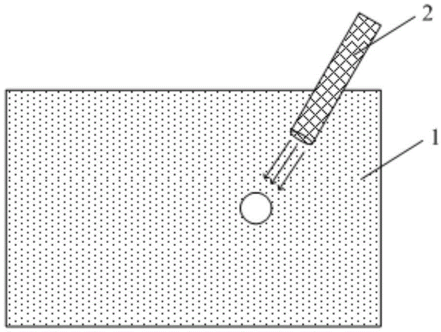
[0028] This embodiment provides a touch screen, including a display substrate and a touch electrode, wherein the touch electrode is formed of an electrode material or a metal material containing a photosensitive substance, and the touch electrode is controlled by a light source control unit that is not in direct physical contact with the touch screen. The touch point is positioned and operated, and the light source control unit has a light source compatible with the photosensitive substance. In this embodiment, "indirect physical contact" means that the touch point position of the touch screen is not caused by direct contact with the touch screen by the human body or a stylus, but by the contact of the touch electrodes caused by the photosensitive reaction. property changes (such as changes in resistance or capacitance), and when the position of the touch point is detected, the subsequent menu command operation mode of the touch point position is not the same as that of the hum...

Embodiment 2

[0042] This embodiment provides a touch screen. The difference between the display screen and the touch screen in Embodiment 1 is that the touch electrodes are capacitive touch electrodes instead of resistive touch electrodes. That is, in this embodiment, the light source of the light source control unit illuminates the touch screen to change the capacitance value of the touch electrode to realize the positioning and operation of the touch point.

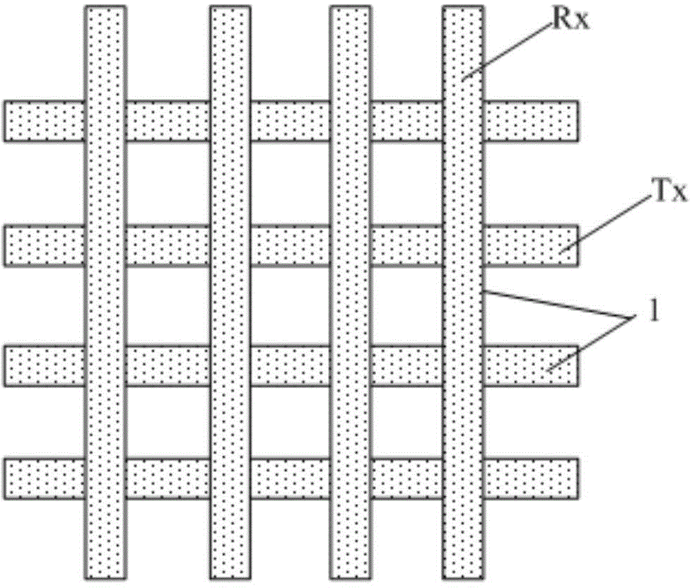
[0043] Wherein, the touch electrode includes a strip-shaped transmitting electrode Tx and a strip-shaped receiving electrode Rx arranged crosswise, and a transparent insulating isolation layer is arranged between the transmitting electrode Tx and the receiving electrode Rx; When the infrared light source irradiates the touch electrode, the capacitance value of the touch electrode changes, wherein the infrared light source emitted by the light source control unit has a wavelength range of 1000-1500 nm.

[0044] The touch principle of...

Embodiment 3

[0048] This embodiment provides a display device, which includes the touch screen in Embodiment 1 or Embodiment 2.

[0049] The display device can be any product or component with a display function such as a liquid crystal panel, an electronic paper, an OLED panel, a mobile phone, a tablet computer, a television, a monitor, a notebook computer, a digital photo frame, a navigator, and the like.

[0050] The display device in this embodiment adopts a touch screen with photosensitive touch function, so that display devices such as TVs and electronic blackboards can conveniently realize remote operations similar to fingers directly touching the touch screen, which is convenient and flexible.


PUM

PropertyMeasurementUnit
Wavelengthaaaaaaaaaa

Abstract

The invention belongs to the technical field of display, and particularly relates to a touch screen and a display device. The touch screen comprises a display substrate and touch electrodes, the touch electrodes are formed by an electrode material or a metal material containing a photosensitive substance and controlled by a light source control unit which does not directly contact with the touch screen physically to realize touch point positioning and operating, and the light source control unit comprises a light source matched with the photosensitive substance. In the touch screen, the touch electrodes are formed by the electrode material or the metal material containing the photosensitive substance, remote operation similar to a finger directly contacting with the touch screen is realized, convenience and flexibility are realized, and application range of the touch screen is extended.

Description

technical field [0001] The invention belongs to the field of display technology, and in particular relates to a touch screen and a display device. Background technique [0002] At present, a large number of various touch screens have appeared, realizing the close-range operation of various display devices (mobile phones, tablet computers, notebook computers, etc.). Touch screens usually use Indium Tin Oxide (Indium Tin Oxide, ITO for short) electrode materials or metal materials as touch electrodes. The touch function is realized by using the change of the resistance value or capacitance value of the touched point in the touch screen when the human hand touches the touch screen. However, the operability of display devices requiring remote operation, such as televisions and electronic blackboards, is still poor. [0003] In occasions such as electronic teaching or exhibition demonstrations, a laser pointer has been used as a long-distance indication method, which usually use...

Claims


Application Information

Patent Timeline
IPC IPC(8): G06F3/044G02F1/1333
CPCG06F3/0442G06F3/0445G06F3/0446
Inventor 古龙云余道平张炜李圭铉
Owner CHONGQING BOE OPTOELECTRONICS
Why Eureka
Try Eureka