Polarization imaging endoscope system and endoscopic imaging method

A polarization imaging and endoscopy technology, applied in endoscopy, medical science, diagnosis, etc., can solve problems such as inability to completely solve, unable to obtain accurate polarization images, and mismatch of front and rear images, and shorten the detection time.

Active Publication Date: 2016-04-20
SHENZHEN GRADUATE SCHOOL TSINGHUA UNIV
View PDF3 Cites 3 Cited by
  • Summary
  • Abstract
  • Description
  • Claims
  • Application Information

AI Technical Summary

Problems solved by technology

In the past, the polarization detection mostly used linearly polarized light, which could only analyze the polarization information of the tissue part, but in order to fully reflect all the polarization information of the tissue, 16 Mueller matrix images of the tissue must be measured.
The traditional method uses time-sharing measurement to obtain 16 Mueller matrix images, which requires a measurement time of 10-60 seconds. Since the operator and the measured object are not stationary during the measurement, such a long measurement often results in front and rear images. Mismatch, can not get accurate polarization image
[0003] Literature AntonelloDeMartino, Yong-KiKim, EnricGarcia-Caurel, BlandineLaude, and Bernard Drévillon, "Optimized Muellerpolarimeterwithliquidcrystals," OpticsLetters, 28 (8) 2003. Disclosed about liquid crystal phase delay method and its optimization method, but still can not completely solve the above problems

Method used


Image

  • Polarization imaging endoscope system and endoscopic imaging method
  • Polarization imaging endoscope system and endoscopic imaging method
  • Polarization imaging endoscope system and endoscopic imaging method

Examples


Embodiment Construction

[0033] The present invention will be further described below in combination with preferred embodiments.

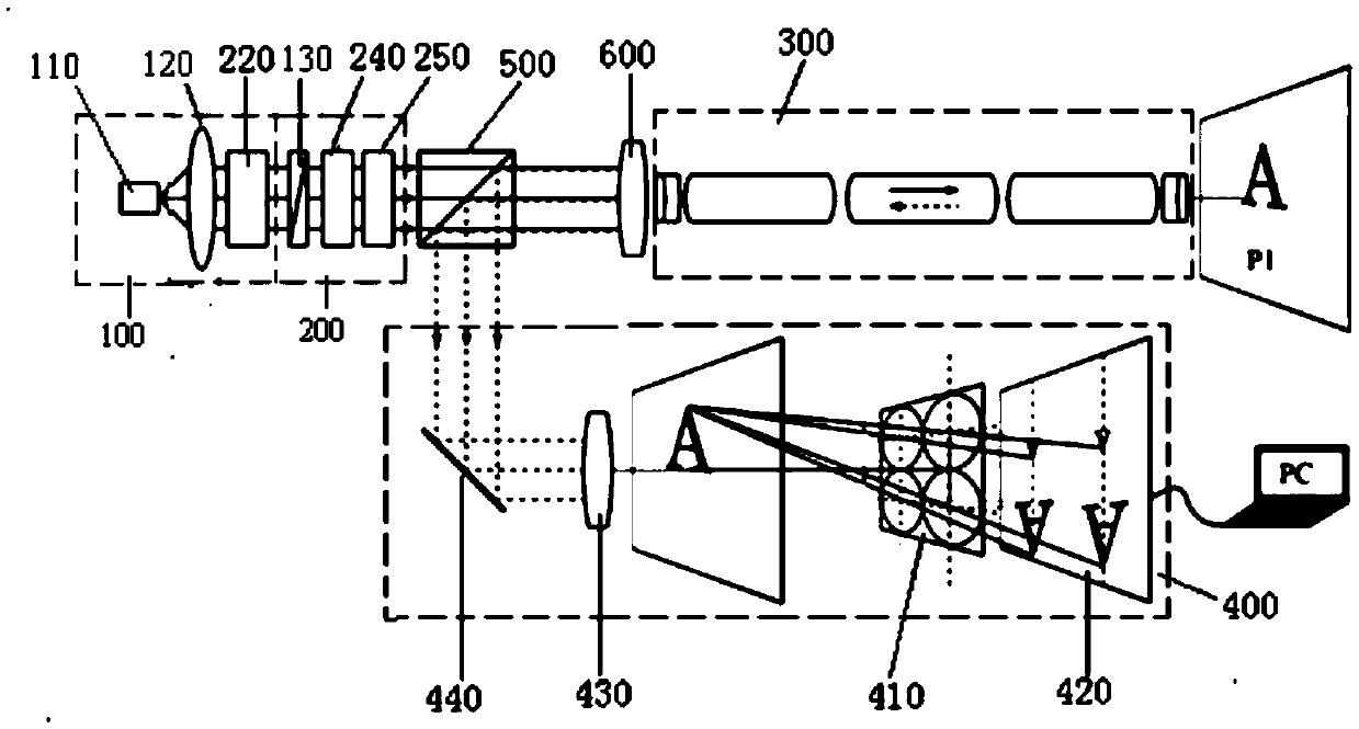
[0034] Such as figure 1 In the specific embodiment shown, the polarized imaging endoscope system includes

[0035] A light source 100; a polarizing device 200, used to sequentially modulate the light from the light source into illumination lights of different polarization states; an endoscope device 300, used to convert the illumination lights of different polarization states from the polarizing device The light is sequentially irradiated onto the surface of the tissue to be photographed; the analyzer 400 is configured to image the light returned from the surface of the tissue to be photographed and record the formed image.

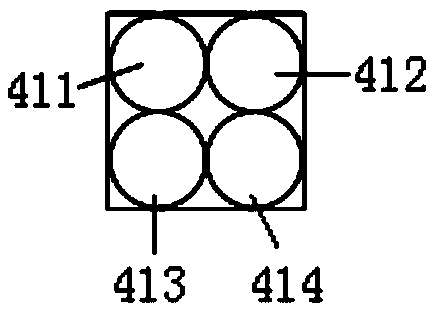
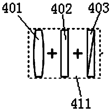
[0036] The polarization analysis camera device 400 includes a polarization analysis lens array 410 and an imaging unit 420 arranged in sequence, and the polarization analysis array 410 includes four polarization analysis array units 411, 412, 413, 41...


PUM


Abstract

The invention discloses a polarization imaging endoscope system and an endoscopic imaging method. The system comprises a light source, a polarizing device, an endoscope device and a polarization analyzing and camera shooting device, wherein the polarizing device is used for modulating light of the light source into illumination light of different polarization states, the endoscope device is used for irradiating the illumination light of the different polarization states from the polarizing device onto the surface of shot tissue, and the polarization analyzing and camera shooting device is used for carrying out imaging on return light of the surface of the shot tissue and carrying out camera shooting on the formed images. The polarization imaging endoscope system is characterized in that the polarization analyzing and camera shooting device comprises a polarization analysis lens array and a camera shooting unit, the polarization analysis lens array and the camera shooting unit are arranged in sequence, and the polarization analysis lens array comprises at least four polarization analysis array units which are respectively used for carrying out analysis and imaging on the light of different polarization states in the return light. The camera shooting unit is used for carrying out camera shooting on the images formed by the four polarization analysis array units. The polarization imaging endoscope system and the endoscopic imaging method have the advantages of achieving polarization imaging rapidly.

Description

technical field [0001] The invention relates to the technical field of endoscope imaging detection, in particular to a polarization imaging endoscope system and an endoscope imaging method. Background technique [0002] In recent years, optical detection methods have been widely used in the field of biomedicine because of their high resolution, no damage to the detection object, and easy implementation. Many international studies have shown that the polarization imaging method can improve the resolution of surface tissue imaging and effectively reflect the morphology and microstructure information of biological tissues. When the tissue becomes lesioned or even cancerous, the change of the polarization image is more sensitive than the ordinary imaging. Therefore, the method of polarization imaging has the potential of interventional endoscopic detection. The previous polarization detection mostly used linearly polarized light, which could only analyze the polarization infor...

Claims


Application Information

Patent Timeline
Patent Type & Authority Patents(China)
IPC IPC(8): A61B1/05
Inventor 马辉常金涛曾楠
Owner SHENZHEN GRADUATE SCHOOL TSINGHUA UNIV
Why Eureka
Try Eureka