Grinding machine

A grinding wheel and grinding wheel technology, which is applied in the field of grinding machines, can solve the problems of high labor strength, no consideration of shock resistance, labor consumption, etc., and achieve the effects of reducing maintenance times, saving labor, and improving sharpening efficiency.

Inactive Publication Date: 2014-11-26
ZHANGJIAGANG HAIXIN HARDWARE PROD
View PDF9 Cites 0 Cited by
  • Summary
  • Abstract
  • Description
  • Claims
  • Application Information

AI Technical Summary

Problems solved by technology

[0002] The world is developing and society is progressing. Since the Industrial Revolution, mechanical production has been flooding people's social production activities. As we all know, the grinder is a relatively widely used mechanical equipment. The traditional grinder needs to be held manually during the sharpening process. It needs to be sharpened, and the strength of holding it for a long time is relatively high, and the traditional grinder does not consider the anti-vibration factor. The strong cracking and vibration of the grinder during work will damage the grinding wheel. For example, the document with the application number 200320108679.3 discloses a hand-held swinging grinding wheel Machine, including a fixed vertical shaft and a grinding wheel mechanism composed of a motor, a pulley, a transmission belt, a swing arm, and a grinding wheel. It consists of a rotating mechanism and an operating armrest rigidly connected to the swing arm. Although the operation is simple and convenient, it requires manpower, and there is no anti-shock structure in the work, which consumes manpower and wears out the machine. The design of the present invention solves the above shortcomings. make up for the above defects

Method used


Image

  • Grinding machine
  • Grinding machine

Examples


Embodiment Construction

[0013] In order to make the technical means, creative features, goals and effects of the present invention easy to understand

[0014] It is clear that the present invention will be further elaborated below in conjunction with specific embodiments.

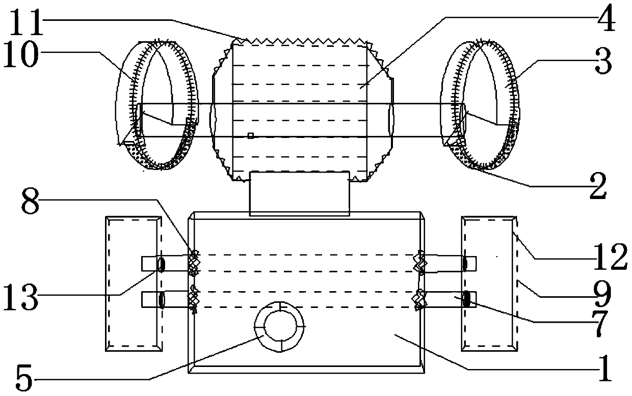
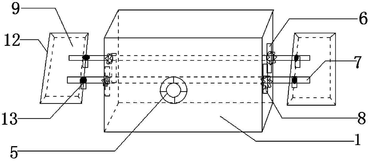
[0015] like figure 1 and figure 2 Shown, a kind of grinding wheel machine comprises base 1, grinding wheel 2, grinding wheel housing 3 and engine 4, and described base 1 is provided with switch 5, and described grinding wheel 2 is connected with engine 4, and described engine 4 is connected with base 1 connection, the base 1 is respectively provided with two bayonet sockets 6 parallel to the grinding wheel 2, the bayonet sockets 6 are provided with a support rod 7, and the support rod 7 is connected with the base 1 by a nut 8, so The supporting rod 7 is provided with a fixed plate 9 at the corresponding position of the grinding wheel 2, and a soft gasket 10 is provided between the grinding wheel 2 and the grinding wheel shell 3...


PUM

PropertyMeasurementUnit
Thicknessaaaaaaaaaa
Heightaaaaaaaaaa

Abstract

The invention discloses a grinding machine and relates to the field of industrial machinery. The grinding machine comprises a base, grinding wheels, grinding wheel casings and an engine. A switch is arranged on the base, and the grinding wheels are connected with the engine connected with the base. Two bayonets are formed in the faces, parallel to the grinding wheels, of the base respectively, supporting rods are arranged in the bayonets, the supporting rods are connected with the base through nuts, fixing plates are arranged at the corresponding positions of the supporting rods and the grinding wheels, soft gaskets are arranged between the grinding wheels and the grinding wheel casings, and the thicknesses of the soft gaskets range from 0.2mm to 0.4mm. The two bayonets, the supporting rods and the fixing plates are arranged, objects with edges to be ground can be fixed in the fixing plates, manual holding can be replaced, and the edge grinding process does not need to be watched by a specially-assigned person so that manpower can be saved, and the full-automatic mechanical process is achieved. The soft gaskets with a shock-resistant function are arranged between the grinding wheels and the grinding wheel casings, the grinding wheels are prevented from being broken due to vibration in the edge grinding process, the grinding wheels can be protected effectively, and the mechanical service life is prolonged.

Description

technical field [0001] The invention relates to the field of industrial machinery, in particular to a grinder. Background technique [0002] The world is developing and society is progressing. Since the Industrial Revolution, mechanical production has been flooding people's social production activities. As we all know, the grinder is a relatively widely used mechanical equipment. The traditional grinder needs to be held manually during the sharpening process. It needs to be sharpened, and the strength of holding it for a long time is relatively high, and the traditional grinder does not consider the anti-vibration factor. The strong cracking and vibration of the grinder during work will damage the grinding wheel. For example, the document with the application number 200320108679.3 discloses a hand-held swinging grinding wheel Machine, including a fixed vertical shaft and a grinding wheel mechanism composed of a motor, a pulley, a transmission belt, a swing arm, and a grindin...

Claims


Application Information

Patent Timeline
IPC IPC(8): B24B3/00B24B41/06
CPCB24B3/00B24B55/00
Inventor 刘刚
Owner ZHANGJIAGANG HAIXIN HARDWARE PROD
Why Eureka
Try Eureka