Method for reinforcement of metal surface by large area laser shock

A laser shock strengthening, metal surface technology, applied in the field of laser processing, can solve the problems of workpiece warping, affecting the impact effect, destroying the absorption layer, etc., to avoid damage, improve bending fatigue strength, and facilitate operation.

Inactive Publication Date: 2014-11-26
JIANGSU UNIV
View PDF5 Cites 18 Cited by
  • Summary
  • Abstract
  • Description
  • Claims
  • Application Information

AI Technical Summary

Problems solved by technology

[0004] However, when performing laser lap impact on thin workpieces, geometric effects have an important impact on the final residual stress distribution. If the lap impact trajectory is unreasonable, edge effects will occur when impacting thin workpieces, namely Residual tensile stress is generated at the edge of the impact area, affecting the impact effect, and even destroying the absorbing layer and causing the workpiece to warp

Method used


Image

  • Method for reinforcement of metal surface by large area laser shock
  • Method for reinforcement of metal surface by large area laser shock
  • Method for reinforcement of metal surface by large area laser shock

Examples


Embodiment 1

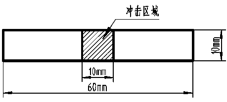
[0027] Example 1, such as figure 2 Laser shock strengthening is performed on the central 10mm×10 mm area of ​​Ti6342 of 60mm×10 mm×2 mm, using a circular spot, and adjusting the laser parameters: laser energy 3J, pulse width 27ns, spot diameter 4mm, energy density 3.5GW / cm 2 , choose 50% lapping rate, repetition frequency 0.5Hz, double-sided shocking method.

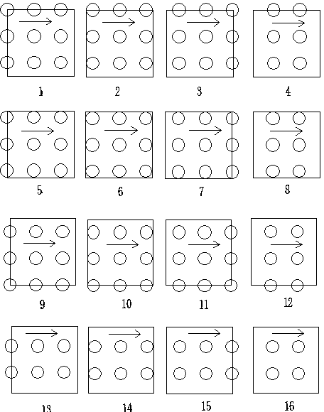
[0028] Clamp the workpiece on the cage, use aluminum foil as the absorption layer, the nozzle hits the sample with water to form a water curtain as the constraint layer, move the X-Y table to change the impact position, the specific impact method is as follows figure 2As shown, 121 light spots are divided into 16 layers for impact. Take the corner of the area to be impacted as the reference point, and use the reference point as the starting point of the first layer of impact. After the initial point impact is completed, control the X-Y table to move horizontally so that the distance between the centers of adjacent lig...

Embodiment 2

[0029] Example 2, such as figure 1 Perform laser shock strengthening on the central 10mm×10 mm area of ​​60mm×10 mm×2 mm Ti6342; use a square spot, adjust the laser parameters as follows: laser energy 13J, pulse width 15ns, spot side length 3mm, overlap rate selection 10% , the repetition frequency is 0.5Hz, and the impact method is double-sided impact.

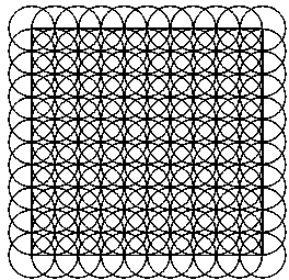
[0030] Clamp the workpiece on the cage, use aluminum foil as the absorption layer, the nozzle hits the sample with water to form a water curtain as the constraint layer, and move the X-Y table to change the impact position; the specific impact method is as follows image 3 As shown, 25 light spots are divided into 9 layers for impact. Take the corner of the area to be impacted as the reference point, use the reference point as the starting point of the first layer of impact, and align the center of the rectangular spot with the starting point. After completing the starting point impact, control the X-Y table to move horizont...


PUM


Abstract

The invention relates to the field of laser processing, and in particular relates to a method for reinforcement of metal surfaces by large area laser shock. The invention adopts laser shock reinforcement for interval shocks on the surface of a workpiece according to a certain trajectory, and large area lap connection shock on the workpiece can be achieved by multilayer stacking. The method can effectively reduce the residual tensile stress generated in the shock region boundary during the laser shock reinforcement, meanwhile avoids the absorption layer destruction and workpiece warpage, and can obtain a uniformly distributed shock reinforcement effect.

Description

technical field [0001] The invention relates to the field of laser processing, in particular to a method for reducing the residual tensile stress generated at the boundary of the impact area by using a laser layered impact method when strengthening a large-area metal surface, and at the same time avoiding the damage of the absorbing layer and the warping of the workpiece. technical background [0002] In the early 1960s, Askaryon et al. first discovered the laser-induced plasma shock wave phenomenon. They irradiated the surface of the metal target with a Q-switched laser, and obtained a shock pressure of about 0.1GPa; Clauer et al. used the metal target surface to add black The impact structure of the coating and the transparent constrained layer, the amplitude of the shock wave is further increased to the GPa level, thus forming the commonly used laser peening method with the constrained layer and the absorbing layer; after that, Clauer et al. For a period of time, the lase...

Claims


Application Information

Patent Timeline
Patent Type & Authority Applications(China)
IPC IPC(8): C21D10/00
Inventor 罗开玉林通鲁金忠
Owner JIANGSU UNIV
Why Eureka
Try Eureka