Tool with TiAIN coating

a technology of tiain coating and tool, which is applied in the direction of superimposed coating process, manufacturing tools, turning machine accessories, etc., can solve the problems of cracks, cracks, wear resistance of tools, adhesion problems, etc., to reduce residual tensile stresses, and increase residual compressive stresses

Active Publication Date: 2020-05-26
WALTER AG
View PDF11 Cites 0 Cited by
  • Summary
  • Abstract
  • Description
  • Claims
  • Application Information

AI Technical Summary

Benefits of technology

[0006]The residual stresses in hard material coatings can have a significant influence on the properties of the coatings with advantageous or disadvantageous effects on the wear resistance of the tool. Residual tensile stresses exceeding the tension limit of the respective material can cause fractures and cracks in the coating perpendicular to the direction of the residual tensile stress. In general, a particular amount of residual compressive stress in the coating is desired, because it avoids and closes surface cracks and improves the fatigue properties of the coating and thereby of the tool. However, too high residual compressive stresses can lead to adhesion problems and to chipping of the coating.
[0007]To increase the residual compressive stresses in the hard material coating of a tool, especially in hard material coatings deposited in the CVD process, it is known to subject the tool to a mechanical surface treatment. Known mechanical treatment methods are the treatment by brushing and dry blasting or wet blasting. In the blasting treatment a fine grained blasting medium is directed onto the surface of the coating using compressed air under increased pressure. Such a surface treatment can reduce residual tensile stresses and increase residual compressive stresses in the outermost layer, but also in the layers of the hard material coating arranged thereunder.
[0008]Single-layer or multi-layer wear protective coatings of tools for the chip forming metal machining often comprise one or more polycrystalline TiAlN and / or TiAlCN layers having predominantly face-centered cubic crystal structure (fcc-TiAlN, fcc-TiAlCN). Especially fcc-TiAlN layers have proven of value for the wear protection of tools for multiple chip forming applications. Compared to the monometallic border systems of the hard material phases fcc-TiN, fcc-TiCN or AlN having hexagonal structure (w-AlN), fcc-TiAlN and fcc-TiAlCN layers are characterized by the advantageous combination of increased hardness and oxidation resistance. Fcc-TiAlN and fcc-TiAlCN layers are thermodynamically metastable. It is known that fcc-TiAlN deposited by PVD processes decomposes at increased temperature first by spinodal decomposition into Al-rich and Ti-rich domains of fcc-AlN and fcc-TiN, respectively. This goes along with an increase of the hardness and is known as “age hardening effect”. When the temperature is further increased, the layer decomposes into the thermodynamically stable phases w-AlN (AlN having wurtzite structure) and fcc-TiN. For example, P. H. Mayrhofer et al., Applied Physics Letters, 83 / 10 (2003), pages 2049-2051, report about a spinodal decomposition of a Ti0.5Al0.5N layer, which is deposited in the PVD process, at 860° C. beginning from the bulk of the coating material. The hardness of the coating decreases beginning at about 850° C., and above about 950° C. it is lower than in the non-annealed state. Adibi et al., J. Appl. Phys., 69 / 9 (1991), pages 6437-6450 report about the PVD deposition of Ti0.5Al0.5N coatings, wherein a surface-initiated spinodal decomposition is observed in a temperature range of 540-560° C., and at a further increase of the temperature a phase separation into fcc-TiN and w-AlN is observed. Significant proportions of w-AlN phase, which is softer than fcc-TiAlN and fcc-TiN phases, lead to unfavorable mechanical and tribological properties of the coating. The phase conversion is promoted by stacking faults.OBJECT OF THE INVENTION
[0009]The object of the present invention was to provide coated tools for the chip forming metal machining, particularly for turning and milling of steel or cast materials, which exhibit, compared to the prior art, improved wear resistance and improved comb crack resistance in dry machining, as well as under the use of coolant.DESCRIPTION OF THE INVENTION
[0010]This object is solved by a tool having a base body of cemented carbide, cermet, ceramics, steel or high-speed steel and a single-layer or multi-layer wear protection coating deposited thereon in the CVD process and having a thickness within the range of from 2 μm to 25 μm, wherein the wear protection coating comprises at least a Ti1-xAlxCyNz layer with 0.40≤x≤0.95, 0≤y≤0.10 and 0.85≤z≤1.15 having a thickness in the range of from 1 μm to 16 μm and having >85 vol-% face-centered cubic (fcc) crystal structure, wherein the tool is characterized in that the Ti1-xAlxCyNz layer comprises precipitations of Ti1-oAloCpNq at the grain boundaries of the Ti1-xAlxCyNz crystallites having a higher Al content than inside the crystallites, wherein 0.95≤o≤1.00, 0≤p≤0.10, 0.85≤q≤1.15 and (0−x)≥0.05.
[0011]A Ti1-xAlxCyNz layer of the inventive stoichiometry, that is deposited in the CVD process on a substrate body, usually exhibits residual tensile stresses after its deposition, as it is the case in most of the hard material layers produced in the CVD process. Tools for the chip forming metal machining having such a layer in the wear protection coating are therefore subject to wear through crack formation, particularly comb crack formation. In the inventive tool, which is produced as it will subsequently be described, in the Ti1-xAlxCyNz layer, because of the precipitations at the grain boundaries, there is generated a residual stress condition, advantageously residual compressive stresses, leading to an improvement of the wear resistance and crack resistance, especially comb crack resistance. This could be proved by experiments comparing coated tools having the same layer sequence and comprising a Ti1-xAlxCyNz wear protection layer without or with the inventive precipitations at the grain boundaries. Compared to the comparative tools, in milling tests the inventive tools exhibited longer service lives, less comb crack formation and high thermal stability of the Ti1-xAlxCyNz wear protection layer.

Problems solved by technology

The residual stresses in hard material coatings can have a significant influence on the properties of the coatings with advantageous or disadvantageous effects on the wear resistance of the tool.
Residual tensile stresses exceeding the tension limit of the respective material can cause fractures and cracks in the coating perpendicular to the direction of the residual tensile stress.
However, too high residual compressive stresses can lead to adhesion problems and to chipping of the coating.
Significant proportions of w-AlN phase, which is softer than fcc-TiAlN and fcc-TiN phases, lead to unfavorable mechanical and tribological properties of the coating.

Method used


Image

  • Tool with TiAIN coating
  • Tool with TiAIN coating
  • Tool with TiAIN coating

Examples


example 1

on of Coated Cemented Carbide Indexable Cutting Inserts and Analysis

[0084]As substrate bodies in these examples cemented carbide indexable cutting inserts of the geometry SEHW1204AFN having a composition of 90.5 wt-% WC, 8 wt-% Co and 1.5 wt-% (NbC+TaC) were used.

[0085]For the coating of the cemented carbide indexable cutting inserts a CVD coating reactor of the type Bernex BPX325S with a reactor height of 1250 mm, a reactor diameter of 325 mm and a volume of the charge arrangement of 40 liters was used. The gas flow was radially with respect to the longitudinal axis of the reactor.

[0086]For the adhesion of the inventive Ti1-xAlxCyNz layer, as well as of the comparative layers, immediately on the cemented carbide substrate there was first deposited an about 0.3 μm thick TiN layer by CVD under the deposition conditions indicated in table 1:

[0087]

TABLE 1Reaction conditions for the preparation of the adhesion layerReaction gasAdhesionTemp.PressureTimemixture [vol-%]Layer[° C.][kPA][min...

example 2

ests

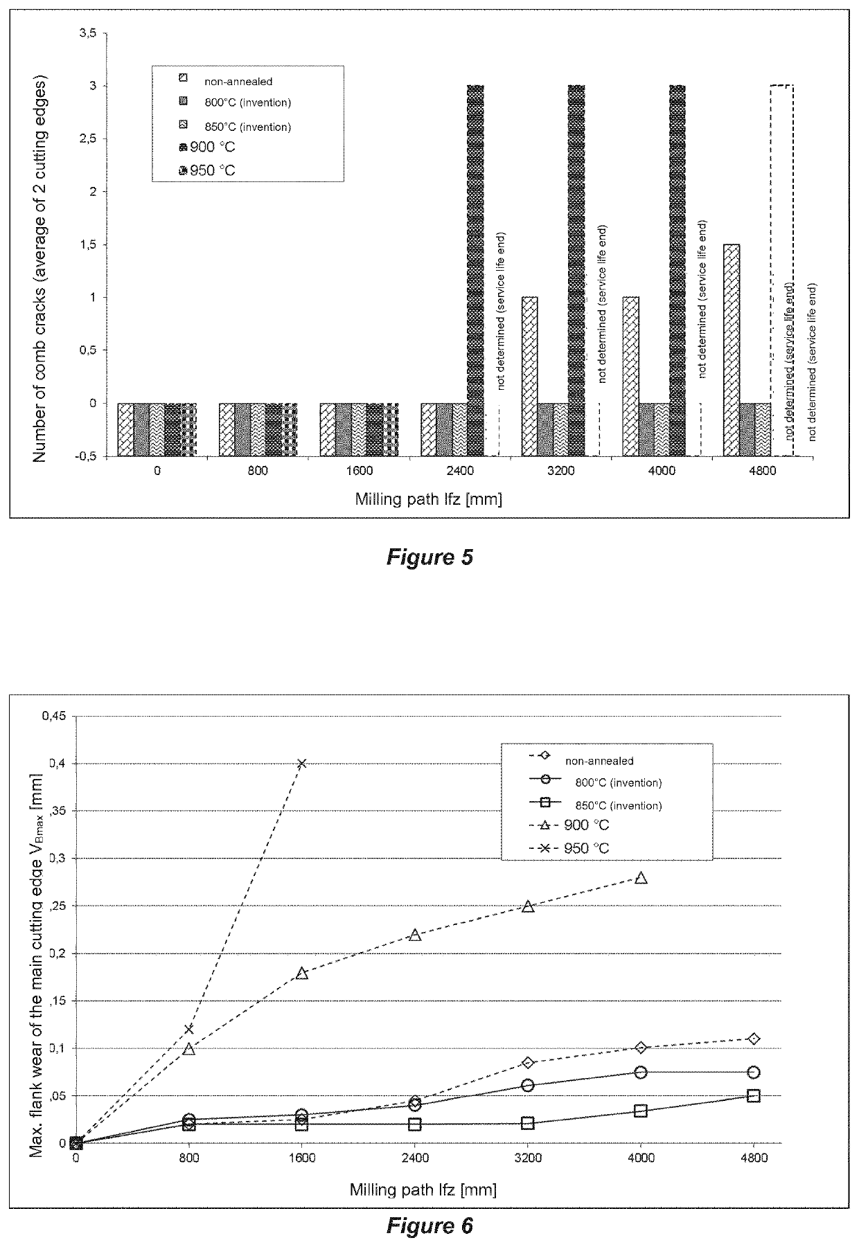
[0097]Using the cemented carbide indexable cutting inserts prepared in example 1 (inventive examples Nos. 8 and 9, and comparative examples Nos. 7, 10 and 11) milling operations were carried out under the following cutting conditions:

[0098]Work piece material: cast iron GG25

[0099]Parallel feed, no coolant used

[0100]Feed per tooth: fz=0.2 mm

[0101]Depth of cut: ap=3 mm

[0102]Cutting speed: vc=283 m / min

[0103]Setting angle: κ=45°

[0104]Milling width: ae=98 mm

[0105]Projection length: ue=5 mm

[0106]The comb crack formation (FIG. 5), the maximum flank wear VB,max (FIG. 6) and the average flank wear VB (FIG. 7) of the tools was determined at the main cutting edge after a milling distance of 800 mm, 1600 mm, 2400 mm, 3200 mm, 4000 mm and 4800 mm, respectively. The results are shown in FIGS. 5, 6 and 7.


PUM

PropertyMeasurementUnit
thicknessaaaaaaaaaa
thicknessaaaaaaaaaa
Vickers hardnessaaaaaaaaaa

Abstract

A tool having includes a base body of cemented carbide, cermet, ceramics, steel or high-speed steel and a single-layer or multi-layer wear protection coating deposited thereon by CVD process and having a thickness within the range of from 2 μm to 25 μm. The wear protection coating has at least a Ti1-xAlxCyNz layer with 0.40≤x≤0.95, 0≤y≤0.10 and 0.85≤z≤1.15 having a thickness in the range of from 1 μm to 16 μm and having >85 vol-% face-centered cubic (fcc) crystal structure. The Ti1-xAlxCyNz layer includes precipitations of Ti1-oAloCpNq at the grain boundaries of the Ti1-xAlxCyNz crystallites have a higher Al content than inside the crystallites, wherein 0.95≤o≤1.00, 0≤p≤0.10, 0.85≤q≤1.15 and (0−x)≥0.05.

Description

RELATED APPLICATION DATA[0001]This application is a § 371 National Stage Application of PCT International Application No. PCT / EP2016 / 065908 filed Jul. 16, 2017 claiming priority to EP 15178477.4 filed Jul. 27, 2015.FIELD OF THE INVENTION[0002]The present invention relates to a tool having a base body of cemented carbide, cermet, ceramics, steel or high-speed steel and a single-layer or multi-layer wear protection coating deposited thereon in the CVD process and having a thickness within the range of from 2 μm to 25 μm, wherein the wear protection coating comprises at least a Ti1-xAlxCyNz layer with 0.40≤x≤0.95, 0≤y≤0.10 and 0.85≤z≤1.15 having a thickness in the range of from 1 μm to 16 μm and having >85 vol-% face-centered cubic (fcc) crystal structure. The present invention further relates to a process for the production of the inventive tool.BACKGROUND OF THE INVENTION[0003]Tools for the chip forming metal machining consist of a substrate body of cemented carbide, cermet, ceram...

Claims


Application Information

Patent Timeline
Patent Type & Authority Patents(United States)
IPC IPC(8): B23B27/14C23C16/36C23C16/34C23C16/56C23C16/40
CPCC23C16/36C23C16/56C23C16/34B23B27/148C23C16/403B23B2228/04B23B2224/32B23B2228/105C23C28/044
Inventor STIENS, DIRKMANNS, THORSTEN
Owner WALTER AG
Why Eureka
Try Eureka