Device and method for testing thermal balance of gas cooker

A technology of gas cooker and testing device, which is applied in the direction of measuring device, calorimeter, measuring heat, etc., can solve the problems of not giving smoke exhaust loss, radiant heat loss and heat conduction loss, etc.

Inactive Publication Date: 2014-11-26
SHANGHAI UNIV
View PDF7 Cites 8 Cited by
  • Summary
  • Abstract
  • Description
  • Claims
  • Application Information

AI Technical Summary

Problems solved by technology

But there is no measurement method for exhaust smoke loss, radiation heat loss and heat conduction loss
There is no such devi

Method used


Image

  • Device and method for testing thermal balance of gas cooker
  • Device and method for testing thermal balance of gas cooker
  • Device and method for testing thermal balance of gas cooker

Examples


Embodiment 1

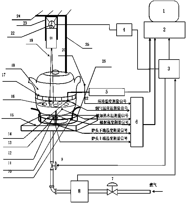
[0072] see figure 1 , the gas cooker heat balance test device, including display (1), computer (2), PLC controller (3), flue gas analyzer (5), multi-channel signal converter (6), gas wet flow meter (8) , solenoid valve (9), radiation intensity sensor (10), temperature sensor at the lower end of the burner (11), temperature sensor at the upper end of the burner (12), water temperature sensor (13), flue gas temperature sensor (14), and the tested cooker ( 15), smoke collector (17), water kettle (18), ambient temperature sensor (20) and radiation intensity sensor bracket (26). It is characterized in that: the ambient temperature sensor (20) is installed in the environment where the kettle (18) is located, the flue gas temperature sensor (14) is installed on the flue gas collector (17), and the flue gas collector (17) is installed on the kettle (18) At the lower flue gas circulation place, the water temperature sensor (13) is fixed on the lid of the kettle (18) and its probe is i...

Embodiment 2

[0074] This embodiment is basically the same as Embodiment 1, and the special features are as follows:

[0075] The water temperature sensor (13) adopts thermal resistance Pt100; the radiation intensity sensor (10) adopts RHFS30; the temperature sensor at the upper end of the burner (12) and the temperature sensor at the lower end of the burner (11) adopt Pt100; the ambient temperature sensor (20) adopt Pt100; the flue gas temperature sensor (41) adopts Pt100; the multi-channel signal converter (6) adopts SQ2040; the PLC controller (3) adopts Xinjie XC3 series PLC; the flue gas Analyzer (5) adopts Siemens testo350 enhanced flue gas analyzer.

Embodiment 3

[0077] see figure 1, the heat balance test device for gas cookers consists of a display (1), a host computer (2), a PLC controller (3), a stepper motor controller (4), a flue gas analyzer (5), and a multi-channel signal converter ( 6), manual valve (7), gas wet flow meter (8), solenoid valve (9), radiation intensity sensor (10), temperature sensor at the lower end of the burner (11), temperature sensor at the upper end of the burner (12), water temperature sensor (13), flue gas temperature sensor (14), tested stove (15), agitator chassis (16), flue gas collector (17), water kettle (18), agitator stick (19), environment Temperature sensor (20), screw rod (21), stepper motor (22), screw rod fixing bracket (23), upper plane (24), upper plane fixing bracket (25) and radiation intensity sensor bracket (26), complete The gas energy consumed by the stove is converted into an estimate of effective absorption energy, flue gas loss energy, radiation loss energy and heat conduction ...


PUM


Abstract

The invention relates to a device for testing thermal balance of a gas cooker, solves the problem of measurement of energy loss in novel cooker design, and provides support for improving cooker design and reducing energy loss. According to the device, based on a combustion principle, by measurement of hot water temperature, smoke component analysis, radiation intensity and temperatures of upper and lower ends of a furnace end, effective heat absorption energy, smoke loss energy, radiation loss energy, and heat conduction loss energy are estimated. By measuring gas flow, total energy of gas consumption is estimated. Thus a main energy consumption proportion of a tested cooker can be obtained, thereby providing test data support for further improving cooker design. The device for testing thermal balance of the gas cooker in the invention adopts computer measurement and control technology, and achieves the effect of automatically realizing signal acquisition, data processing and data management functions. And automated testing of cooker energy conversion and distribution is realized.

Description

technical field [0001] The invention relates to a heat balance test device and method of a gas cooker, and is an automatic test device and a calculation method for estimating energy efficiency and heat loss of a gas cooker. It belongs to the technical field of thermal measurement and control. Background technique [0002] During the development process of domestic gas cookers, it is necessary to guide the design and transformation of domestic gas cookers by estimating indicators such as smoke exhaust loss, radiant heat loss, heat conduction loss, and effective heat absorption. [0003] At present, the national standard GB16410-2007 stipulates the test method for the effective utilization rate of household gas stoves. However, the measurement methods of exhaust smoke loss, radiation heat loss and heat conduction loss are not given. Because there are no sensors for directly measuring exhaust smoke loss, radiant heat loss, and heat conduction loss, there is no such device at...

Claims


Application Information

Patent Timeline
IPC IPC(8): G01K17/00G05B19/05
Inventor 邹斌刘如意王肖李明洋董毅超
Owner SHANGHAI UNIV
Why Eureka
Try Eureka